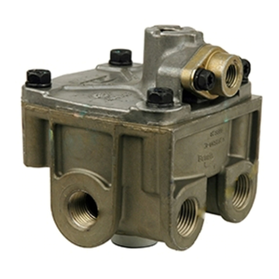
BENDIX R-12DC Руководство - Страница 4
Просмотреть онлайн или скачать pdf Руководство для Блок управления BENDIX R-12DC. BENDIX R-12DC 8 страниц. Relay valve with biased double-check
Также для BENDIX R-12DC: Служебные данные (8 страниц), Инструкции по установке (4 страниц)

Key No.
DESCRIPTION
1
VALVE COVER
2
VALVE SPRING
3
CHECK VALVE GUIDE
4
CHECK VALVE
5
O-RING
6
DOUBLE CHECK COVER
7
O-RING
8
O-RING
9
RELAY PISTON
10
VALVE BODY
11
INLET & EXHAUST VALVE
12
VALVE RETAINER
13
SPRING
14
O-RING
15
O-RING
16
EXHAUST COVER
17
RETAINING RING
18
DIFFERENTIAL SPRING (IF USED)
DIFFERENTIAL SPRING
(CONTROLS CRACK PRESSURE*)
(NOT REQUIRED FOR MOST
SEE BELOW.)
DIFFERENTIAL SPRINGS
*Crack Pressure is the amount of control
pressure required by the valve to initiate
air delivery. For Crack pressures other
than 4 psi, a differential spring is used in
the assembly to produce the required
valve response.
(Models designed to have a 4 psi crack
pressure do not require a differential spring.)
FIGURE 7 - R-12DC
™
EXPLODED VIEW
Caution: Drain all reservoirs before attempting to remove
the inlet exhaust valve.
DISASSEMBLY
Note: Prior to disassembly, mark the location of the
mounting bracket to the cover and the cover to the body.
CAUTION: The valve body may be lightly clamped in a bench
vise during disassembly, however, over-clamping will result
in damage to the valve and result in leakage and/or
malfunction. If a vise is to be used, position the valve so
that the jaws bear on the supply ports on opposing sides of
the valve's body.
4
18
MODELS.
HORIZONTAL
DELIVERY
PORTS
1
VERTICAL
DELIVERY
PORTS
1. Remove the four cap screws securing the mounting
bracket and cover to the body. Retain the cap screws
for reuse.
2. Discard the mounting bracket.
3. Remove and discard sealing ring (7) from the cover (1).
a. Remove the 2 torx screws securing the double check
cover (6) to the cover (1).
b. Remove the double check cover (6) from cover (1)
and remove and discard spring (2), guide (3), double
check diaphragm (4), and o-ring (5).
4. Remove and discard sealing ring (7) from the cover (1),
and mounting bracket.
CAP SCREW
PRIMARY CONTROL
PORT 1/4 NPT
3
2
5
4
6
7
SECONDARY
8
CONTROL PORT
1/4 NPT
9
10
SUPPLY
PORT
11
12
13
14
15
16
17
CAP
SCREW
