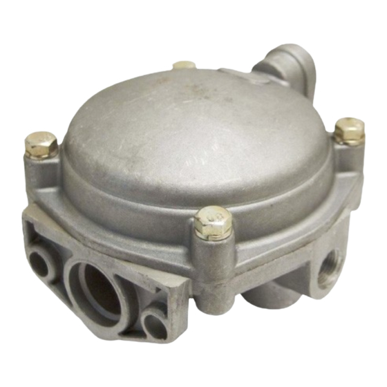
BENDIX R-6 RELAY VALVE Руководство - Страница 3
Просмотреть онлайн или скачать pdf Руководство для Блок управления BENDIX R-6 RELAY VALVE. BENDIX R-6 RELAY VALVE 6 страниц. Relay valve

INSTALLING
Clean air lines connecting to valve.
Inspect all lines and/or hoses for damage and replace as
necessary.
Install valve and tighten mounting bolts.
Connect air lines to valve (Plug any unused ports).
Test valve as outlined in "Operating and Leakage Tests."
DISASSEMBLY
NOTE: Prior to disassembly, mark location of cover to body
to facilitate assembly.
1. Remove cover cap screws (1). Remove cover (2) with
relay piston (4) and spring (6) (if so equipped).
2. Remove relay piston (4) from cover.
3. Remove piston o-ring (3) from piston (4) and cover seal
o-ring from body.
4. Remove exhaust cover cap screws, (19) exhaust cover,
and remove inlet/exhaust valve insert (8) from body(7).
5. Remove exhaust seat (5) from relay piston (4) and
exhaust check valve(18). (Remove only if new parts are
to be installed).
INLET/EXHAUST VALVE INSERT DISASSEMBLY
NOTE: If complete inlet/exhaust valve is replaced, disregard
steps 6 to 9.
6. Depress and hold valve guide down against valve spring
tension and remove retainer (16).
7. Remove valve insert seal o-ring (13), valve guide (14),
spring (12), and valve retainer (11).
8. Remove the inlet/exhaust valve (9) from its body (10).
9. Remove inner o-ring (15) from valve guide (14).
CLEANING AND INSPECTION
Wash all metal parts in mineral spirits; wipe all rubber parts
dry. Inspect all parts for signs of wear and/or deterioration.
Inspect springs for cracks, distortion or corrosion.
Inspect inlet seat and exhaust seat for nicks and burrs and
replace as necessary. It is recommended that all rubber
parts be replaced, and that any part showing signs of wear
or deterioration be replaced.
ASSEMBLY
NOTE: All torques specified in this manual are assembly
torques and can be expected to fall off after
assembly. Do not retorque after initial assembly
torques fall. (For assembly, hand wrenches are
recommended)
1. Prior to assembly, lightly lubricate the relay piston guide
post, o-rings, cover bore and inlet body with Dow Corning
Silicone 55-M Pneumatic grease (Bendix Pc. No.
291126).
INLET/EXHAUST VALVE ASSEMBLY
NOTE: If new inlet/exhaust valve assembly insert is used,
disregard Steps 2 to 6.
2. Install inlet/exhaust valve (9) over valve body (10), smooth
surface up.
3. Position valve retainer (11) over inlet valve body (10) and
valve.
4. Install inlet valve spring (12) over inlet body (10) and install
o-ring (15) in the inner groove in the valve guide (14).
5. Depress and hold guide down against inlet spring and
install retainer ring (16) (A 9/16" twelve point socket can
be used to push the retainer ring down until it snaps in
the groove in the inlet valve body).
6. Install valve insert seat o-ring (13).
COMPLETE VALVE ASSEMBLY
7. Install insert (8) in valve body (7), install exhaust cover
(17) and secure with 10-24 screws (19) torque to
approximately 20-30 inch pounds.
8. Install exhaust check diaphragm (18) into exhaust cover
(17).
9. Install cover seal o-ring.
10. Install relay piston o-ring (3) on relay piston (4), then
position relay piston in cover.
11. If valve utilizes relay piston spring (6) position spring
over guide in body.
12. Position cover/relay piston assembly in correct relative
position with body; if equipped with piston return spring,
make sure exhaust seat is centered inside spring.
13. Install cover cap screws. Torque to approximately 80-120
inch pounds.
14. Test valve as outlined in "Operating and leakage Tests"
section.
WARNING! PLEASE READ AND FOLLOW
THESE
INSTRUCTIONS
PERSONAL INJURY OR DEATH:
When working on or around a vehicle, the following
general precautions should be observed at all times.
1. Park the vehicle on a level surface, apply the
parking brakes, and always block the wheels.
Always wear safety glasses.
TO
AVOID
3
