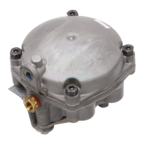
BENDIX RE-6 RELAY EMERGENCY VALVE Руководство - Страница 5
Просмотреть онлайн или скачать pdf Руководство для Блок управления BENDIX RE-6 RELAY EMERGENCY VALVE. BENDIX RE-6 RELAY EMERGENCY VALVE 13 страниц. Relay valves

RE-6
™
& RE-6NC
™
VALVES SERVICE
APPLICATION
During normal, service braking operation, the valve serves
as a relay valve, synchronizes tractor service (application)
RESERVOIR
70 PSI
RE-6NC
FIGURE 7 RE-6NC
™
RELAY VALVE CHARGING ABOVE 70
PSI
air pressure with trailer service (application) air pressure
as the service foot brake valve on the tractor is operated.
If the tractor is equipped with a trailer hand (TC) valve, the
trailer brakes can be applied independently of the tractor
CHAMBER
APPLICATION
10 PSI
FIGURE 8 RE-6
™
& RE-6NC
APPLICATION
brakes. Air is applied to the control port of the RE-6
™
RE-6NC
valves, acting on the primary piston and moving
the inlet / exhaust valve away from the seat on the
emergency piston. Service application allows air to fl ow
from the reservoir, past the shoulder (on the emergency
piston) to the underside of the relay piston and on to the
service chambers to apply the brakes. Refer to Figure 8.
™
™
RE-6
& RE-6NC
VALVES SERVICE HOLD
Air is still being applied to the control port of the RE-6
™
and RE-6NC
valves, but the relay piston has moved
EMERGENCY
SUPPLY
70 PSI
™
Relay Valve
SERVICE
BRAKE
APPLICATION
10 PSI
™
RELAY VALVES SERVICE
CHAMBER
HOLD 5 PSI
FIGURE 9 RE-6
HOLD
enough to allow the inlet / exhaust valve to re-seat on the
emergency piston and close the inlet / exhaust valve. Air
is trapped between the seal of the emergency piston and
inlet / exhaust valve and the service chambers, making the
service brake application. The entrapment of air constitutes
the holding position of the valve. At this time, no air is
fl owing through the valve. Refer to Figure 9.
FIGURE 10 RE-6
EXHAUST
RE-6
™
& RE-6NC
When air is removed from the control port of the RE-6
™
and
™
RE-6NC
valves, the relay piston moves upward. As the
air is let off the control port, the relay piston moves from
its seat on the inlet / exhaust valve, opening the exhaust
path to atmosphere. Air fl ows from the service chambers,
past the relay piston, through the emergency piston and
inlet / exhaust valve to atmosphere past the diaphragm.
Refer to Figure 10.
™
™
™
& RE-6NC
RELAY VALVES SERVICE
0 PSI
™
& RE-6NC
™
RELAY VALVES SERVICE
™
VALVES SERVICE EXHAUST
SERVICE
HOLD
5 PSI
NO AIR FLOW
™
and
5
