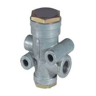
BENDIX TR-3 Руководство - Страница 4
Просмотреть онлайн или скачать pdf Руководство для Блок управления BENDIX TR-3. BENDIX TR-3 4 страницы. Inversion valves
Также для BENDIX TR-3: Служебные данные (4 страниц)

REMOVAL AND INSTALLATION
REMOVAL
Block and hold vehicle by means other than air brakes. Drain
service and emergency or parking reservoirs. Disconnect
air lines from valve. Remove the mounting bolts, remove valve.
INSTALLATION
Remount valve securely using holes provided in body. Check
and clean air lines and reconnect.
DISASSEMBLY
NOTE: Care should be taken if body is clamped in vise.
Excessive tightening can cause distortion of valve
body.
™
TR-2
INVERSION VALVE
1. Remove the cap nut with sealing ring, remove sealing ring
from cap nut.
2. Remove the inlet/exhaust valve spring and inlet/exhaust
valve.
3. Turn the valve over and remove the exhaust diaphragm
cap screw with lockwasher, then the diaphragm washer
and diaphragm.
4. With a pair of #1 Truarc pliers, remove the retainer ring.
Remove the cover plate and two (2) piston springs.
5. Remove the piston with grommets.
6. Remove the piston grommets.
™
TR-3
INVERSION VALVE
1. Remove the exhaust port cap nut and o-ring.
2. Remove the diaphragm retainer and piston spring.
3. Remove the shim washer or washers (if present).
4. Remove the piston from the valve body.
5. Remove the piston o-ring and exhaust stem o-ring.
6. Remove the supply cap nut and o-ring.
7. Remove the valve stop and spring.
8. Remove the inlet and exhaust valve.
™
TR-4
INVERSION VALVE
1. Press lever pin out of the lever and remove lever.
2. Remove the plunger and plunger return spring from cover.
3. Remove the cover nut lock nut.
4. Remove the cover nut and o-ring.
5. Remove the cover and shim washer or washers.
6. Remove the piston spring and piston from body.
7. Remove the piston and exhaust stem o-rings.
8. Remove the supply port cap nut and o-ring.
9. Remove the valve stop and valve return spring.
10. Remove the inlet and exhaust valve.
CLEANING AND INSPECTION
Wash all metal parts in a good cleaning solvent. Rubber
parts should be wiped clean.
Inspect all parts for signs of wear or deterioration. Check
the springs for cracks, corrosion, or distortion. Inspect the
piston and its exhaust seat, body bores, and inlet valve for
nicks, scratches, or burrs.
Replace all parts not considered serviceable during
inspection.
4
BW1581 © 2004 Bendix Commercial Vehicle Systems LLC. All rights reserved. 4/2004 Printed in U.S.A.
ASSEMBLY
Before assembling the valve, lubricate the piston o-rings and
body bores with Bendix silicone lubricant such as BW650M
Bendix Pc. No. 291126.
™
TR-2
INVERSION VALVE
1. Install the piston grommets on piston.
2. Install the piston with grommets in valve body.
3. Position the piston springs, cover plate and retainer ring
in the piston in that order. Press the cover and retainer
down and with a pair of Truarc #1 pliers, snap the ring
into the body groove.
4. Install the diaphragm and diaphragm washer and secure
with cap screw.
5. Turn the inversion valve over and position the inlet and
exhaust valve in its bore.
6. Place the spring over inlet valve.
7. Install the sealing ring on cap nut. Install the cap nut with
sealing ring and tighten securely. Torque to approx. 125
in. lbs.
8. Using the mounting nut and lockwasher, install the valve
on vehicle.
™
TR-3
INVERSION VALVE
1. Install the inlet and exhaust valve in the body (supply
port).
2. Install the inlet valve spring and valve stop (center stop on
spring).
3. Install the o-ring on the supply cap nut and install and
tighten the cap nut. Torque to approx. 100 in. lbs.
4. Install the piston and exhaust stem o-ring on piston. Install
the piston in body.
5. Install the shim washer or washers (if present). Install the
piston spring.
6. Install the diaphragm retainer and exhaust diaphragm.
7. Install the o-ring on exhaust cap nut and install and tighten
the cap nut. Torque to approx. 275 in. lbs.
™
TR-4
INVERSION VALVE
1. Replace the inlet and exhaust valve.
2. Install the valve return spring and valve stop.
3. Install the o-ring on supply cap nut and install and tighten
the cap nut. Torque to approx. 100 in. lbs.
4. Install the piston and exhaust stem o-ring on the piston.
Install the piston in the body.
5. Install the piston spring.
6. Install the cover and washer or washers.
7. Replace the cover nut o-ring on the cover nut and install
and tighten the cover nut. Torque to approx. 275 in. lbs.
8. Install the plunger return spring and plunger.
9. Install the cover nut lock nut. Torque to approx. 100 in.
lbs.
10. Install lever and press the lever pin in to secure.
TESTING REBUILT VALVES
Perform operating and leakage tests as outlined in "Operating
and Leakage Tests" section.
