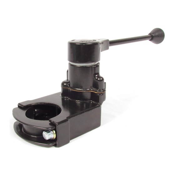
BENDIX TC-2 Инструкции по установке - Страница 3
Просмотреть онлайн или скачать pdf Инструкции по установке для Автомобильные аксессуары BENDIX TC-2. BENDIX TC-2 4 страницы. Trailer control valve maintenance kit

ASSEMBLY
Prior to assembly, lubricate the body and cover bores, cam
and cam follower, piston o-ring, and cover top with Dow
Corning
55-M pneumatic grease (Bendix piece number
®
291126).
1. Press inlet valve on stem. A little water in the boot
valve or some soap on the stem will make it easy to
press on the inlet valve.
2. Place stem with inlet valve installed in the inlet seat.
Insert some object – such as a cap screw – to hold
the inlet valve up against its seat.
3. Position the spring and the exhaust valve guide.
4. Depress the guide and the spring, then press the
exhaust valve on the stem.
5. Place the seal o-ring over the insert seat. Install the
inlet and exhaust insert in the body, securing with cap
screws and lock washers. Recommended torque on
the insert cap screws is 60 to 80 in-lbs.
6. Install the piston return spring.
7. Install the piston o-ring on the piston and install the
piston in the body.
8. Install the adjusting ring in the cover and screw it down
until it is flush with the top of the cover.
9. Place the cam follower and cam in the cover.
10. Position the graduating spring and gasket in the body.
11. Connect the body to the cover; tighten the cap screws
evenly and torque to 75-95 in-lbs.
12. Install the adjusting ring lock washer, head seal o-ring,
and head.
13. Install the set screw in the head of the remote-operated
type valves.
At this stage, before installing the handle and the spirol pin
of the handle-operated type valve, if facilities are available,
the rebuilt valve should be tested and adjusted. If facilities
are not available, the valve can be tested on the vehicle.
ADJUSTABLE
Generally, the Bendix
TC-2
®
full reservoir pressure; however, there are a few exceptions
in special applications.
1. If the delivered pressure is below the specified final
delivery pressure, it can be adjusted by removing the
head and adjusting the ring lock washer and rotating the
adjusting ring clockwise to raise the delivery pressure.
Care should be taken not to raise the delivery pressure
beyond the design limits; exhaust opening could be
restricted.
Brake Valve should deliver
™
2. If the delivery pressure is above the specified final
delivery pressure, it can be lowered by rotating the
adjusting ring counterclockwise.
A spanner wrench can be used to rotate the adjusting ring,
but if this wrench is not available, the adjusting ring can
be turned with a small screwdriver inserted in one of the
inner notches of the ring. Turning the adjusting ring one
notch will raise the delivered pressure approximately 5 psi.
INSTALLATION
1. Check and clean the air lines to the valve.
2. The operating mechanism for remote type should be
checked for functionally and for proper adjustment.
3. Mount the valve with clamp and mounting bolts.
4. Tighten the mounting bolts evenly to approximately 200
in-lbs torque (3/8-16 Bolt torque 180-220 in-lbs).
5. If remote type valve, connect the operating mechanism.
OPERATING TEST
Connect an accurate test gauge to a delivery port. When
the handle is moved to the fully applied position, the gauge
should register full reservoir pressure.
Note:
Some valves may be preset to deliver lower than
reservoir pressure; however, the standard valves
generally used on tractors are set to deliver full
reservoir pressure.
Intermediate positions should deliver proportionate
intermediate pressure. Upon release, the gauge should
immediately register zero.
LEAKAGE TEST
Locate the exhaust port or the exhaust line and apply a
soap solution. (It is common practice to connect a line
from the valve exhaust port to a location remote from the
immediate driver's area.) With the valve in the released
position, exhaust leakage should not exceed a 1 inch bubble
in 5 seconds (100 sccm).
With the valve fully applied, leakage at the exhaust should
not exceed a 1 inch bubble in 3 seconds (175 sccm).
3
