dymax ACCU-CAL 50-LED Руководство пользователя - Страница 9
Просмотреть онлайн или скачать pdf Руководство пользователя для Измерительные приборы dymax ACCU-CAL 50-LED. dymax ACCU-CAL 50-LED 16 страниц. Led radiometer

Testing a Line Array System
1.
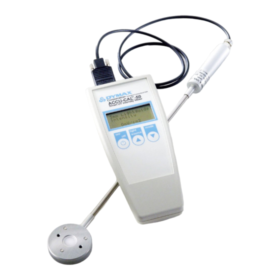
Attach the detector to the radiometer (Figure 10).
2.
Select the line array adapter.
3.
Install the line array adapter onto the detector face using the
two 2-mm screws provided (Figure 12).
Note: Do not over-tighten the set screw, as damage to the
lightguide may occur.
4.
Press and release the On/Off button on the radiometer's face
plate to turn the unit on.
5.
On the radiometer's display, the top line displays the light
source and the second line displays the mode.
•
Repeatedly press and release the Light Source button
until "Line Array" is displayed in the top line of the
display.
6.
Press and release the Mode button to select the operating
mode. Repeatedly press the Mode button until the mode you
desire appears on the second line of the display. The
different operating modes are:
•
Peak Intensity - Shows the highest intensity in mW/cm
seen by the detector during the measurement and
stores that value in the display.
•
Intensity - Shows the intensity in mW/cm
during the measurement. This is a dynamic readout of
intensity.
•
Dose - Shows the total energy dose in mJ/cm
detector during the measurement.
Note: This measurement is time dependent.
Taking Measurements
•
Static readings for general process control when emitter
and target are fixed and working distances are greater than
0 mm:
1. Using a fixed location in the field of the array emissions,
place the aperture of the adapter as close to center as
allowable.
Note: Repeatable placement is key to getting
consistent readings at working distances beyond
direct measurement at the emitter face. An alignment
fixture can help ensure accuracy at these working
distances.
U S E R G U I D E
A C C U - C A L ™ 5 0 - L E D R A D I O M E T E R
|
Figure 10.
Attach Detector to Radiometer
Figure 11.
Line Array Adapter
2
Figure 12.
Adapter Installation
2
at the detector
2
at the
Figure 13.
Line Array Source Screen
(Shown in Intensity Mode)
9
