GAC ESD-5570 Series Руководство - Страница 5
Просмотреть онлайн или скачать pdf Руководство для Блок управления GAC ESD-5570 Series. GAC ESD-5570 Series 8 страниц. Speed control unit
Также для GAC ESD-5570 Series: Техническая информация (12 страниц), Руководство (8 страниц)
5
ADJUSTMENTS - CONTINUED
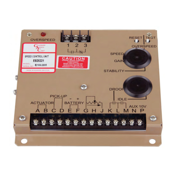
aDJUSTInG overSPeeD
The overspeed relay output terminals offer both normally open and normally closed contacts.
1.
When the engine is running at the desired speed, push and hold the TEST button.
2.
Rotate the OVERSPEED adjustment CCW until the red OVERSPEED LED lights and the
relay energizes. Current to the actuator will be removed and the engine will shut off.
3.
Release the TEST button.
4.
After the engine stops, press the RESET button or remove battery power.
5.
Restart the engine and it will return to the original speed setting.
The overspeed function is now set to approximately 10% above the requested speed.
STarTInG fUeL aDJUSTmenT
The engine's exhaust smoke at start-up can be minimized by completing the following adjustments:
1.
Place the engine in idle by connecting Terminals M & G.
2.
Adjust the IDLE speed for as low a speed setting as the application allows.
3.
Adjust the STARTING FuEL CCW until the engine speed begins to fall. Increase the STARTING FuEL slightly so that the idle speed
is returned to the desired level.
4.
Stop the engine.
IDLe SPeeD SeTTInG
If the IDLE speed setting was not adjusted as detailed in Starting Fuel Adjustment section, then complete the following:
1.
Place the optional external selector switch in the IDLE position.
2.
Adjust the IDLE CW yo increase the idle speed set point.
3.
When the engine is at idle speed, the speed control unit applies droop to the governor system to ensure stable operation.
aDJUSTInG STaBILITY
The governed speed set point is increased by a CW rotation of the SPEED adjustment control (25 turn pot.). Remote speed adjustment
can be obtained with an optional 5K Speed Trim Control. See section 4, Wiring diagram.
Once the engine is at operating speed and at no load, the following governor performance adjustment can be made.
ParameTer
1.
Rotate the GAIN adjustment clockwise until instability develops.
GAIN
2.
Gradually move the adjustment counterclockwise until stability returns.
3.
Move the adjustment one division further counterclockwise to ensure stable performance (270° potentiometer).
4.
If instability persists, adjust the next parameter.
STABILITy
1.
Rotate the STABILITy adjustment clockwise until instability develops.
2.
Gradually move the adjustment counterclockwise until stability returns.
3.
Move the adjustment one division further counterclockwise to ensure stable performance (270° potentiometer).
Normally, adjustments made at no load achieve satisfactory performance. If further performance improvements are required,
noTe
refer to section 7, SySTEM TROuBLESHOOTING.
ProceDUre
5
ESD5550-5570 Series Speed Control Unit 1-2021-E1 PIB1003
Governors America Corp. © 2021 Copyright All Rights Reserved
SPEED
OVERSPEED
ON
1
2
GAIN
STABILITY