GAC ESD5151 Краткое руководство по эксплуатации
Просмотреть онлайн или скачать pdf Краткое руководство по эксплуатации для Блок управления GAC ESD5151. GAC ESD5151 6 страниц. Speed control unit
E
NGINE
G
OVERNING
S
YSTEM
INSTAllATION
The ESD5100 Series speed control unit is rugged enough
to be placed in a control cabinet or engine mounted enclo-
sure with other dedicated control equipment. If water, mist,
or condensation may come in contact with the controller, it
should be mounted vertically. This will allow the fluid to drain
away from the speed control unit. Extreme heat should be
avoided.
⚠
An overspeed shut down device, indepen-
dent of the governor system, should be
provided to prevent loss of engine control,
which may cause personal injury or equip-
ment damage. Do not rely exclusively on the
governor system electric actuator to prevent
overspeed. A secondary shut off device,
such as a fuel solenoid, must be used.
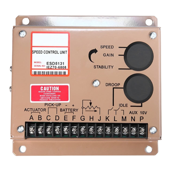
Basic electrical connections are illustrated in Diagram 2. Ac-
tuator and battery connections to Terminals A, B, E, and F
should be #16 AWG (1.3 mm sq.) or larger. Long cables
require an increased wire size to minimize voltage drops.
The battery positive (+) input, Terminal F, should be fused for
15 amps as illustrated. The ESD5100 series is suitable for
12 VDC and 24 VDC operation.
Magnetic speed sensor wires connected to Terminals C and
D MUST BE TWISTED AND/OR SHIELDED for their entire
length. The speed sensor cable shield should ideally be
connected as shown in Diagram 2. The shield should be
insulated to insure no other part of the shield comes in con-
tact with engine ground, otherwise stray speed signals may
be introduced into the speed control unit. With the engine
stopped, adjust the gap between the magnetic speed sensor
and the ring gear teeth. The gap should not be any smaller
than 0.020 in. (0.45 mm). Usually, backing out the speed
sensor 3/4 turn after touching the ring gear teeth will achieve
a satisfactory air gap. The magnetic speed sensor voltage
should be at least 1 VAC RMS during cranking.
ADjUSTMENTS
Before Starting Engine
Check to insure the GAIN and STABILITY adjustments, and
if applied, the external SPEED TRIM CONTROL are set to
mid position.
Speed Control Unit
WARNING
WIRING
Governors America Corp., 720 Silver Street Agawam, MA 01001
phone: 413.786.5600
www.governors-america.com
ESD5100 Series
The speed control unit governed speed setting is factory set
at approximately engine idle speed. (1000 Hz., speed sen-
sor signal)
Crank the engine with DC power applied to the governor sys-
tem. The actuator will energize to the maximum fuel position
until the engine starts. The governor system should control
the engine at a low idle speed. If the engine is unstable after
starting, turn the GAIN and STABILITY adjustments counter-
clockwise until the engine is stable.
The governed speed set point is increased by clockwise ro-
tation of the SPEED adjustment pot. Remote speed adjust-
ment can be obtained with an optional 5K Speed Trim Con-
trol. (See Diagram 2)
Once the engine is at operating speed and at no load, the
following governor performance adjustment can be made.
A. Rotate the GAIN adjustment clockwise until instability
develops. Gradually move the adjustment counterclock-
wise until stability returns. Move the adjustment one
division further counterclockwise to insure stable perfor-
mance (270° pot).
B. Rotate the STABILITY adjustment clockwise until insta-
bility develops. Gradually move the adjustment coun-
terclockwise until stability returns. Move the adjustment
one division further to insure stable performance (270°
pot).
C. Gain and stability adjustments may require minor chang-
es after engine load is applied. Normally, adjustments
made at no load achieve satisfactory performance. A
strip chart recorder can be used to further optimize the
adjustments.
If instability cannot be corrected or further performance im-
provements are required, refer to the SYSTEM TROUBLE-
SHOOTING section. In this section, information can be found
regarding troubleshooting procedures as well as instructions
on adjusting the DIP switch positions of the ESD5131.
After the governor speed setting had been adjusted, place
the optional external selector switch in the IDLE position.
The idle speed set point is increased by clockwise of the
IDLE adjustment control. When the engine is at idle speed,
the speed control unit applies droop to the governor System
to insure stable operation.
fax: 413.789.7736
1
Start Engine
Governor Speed Setting
Governor Performance
Idle Speed Setting
G
OVERNORS
A
MERICA
C
ORP.
®
ISO 9001
CERTIFIED