GAC ESD5526E Руководство - Страница 6
Просмотреть онлайн или скачать pdf Руководство для Блок управления GAC ESD5526E. GAC ESD5526E 9 страниц. Speed control unit
Также для GAC ESD5526E: Руководство (9 страниц)
11
ADDITIONAl FEATURES AND OPTIONAl WIRINg
IDLe SPeeD SettInG
5.500
If the IDLE speed setting was not adjusted as detailed in Section 9 Starting
(140)
Fuel Adjustment, then place the optional external selector switch in the IDLE
position.
5.000
The idle speed set point is increased by the clockwise rotation of the IDLE
adjustment control. When the engine is at idle speed, the speed control unit
applies droop to the governor system to ensure stable operation.
If not using the idle method, you can lower idle to the bare minimum (even if it's
not being used) for smoke reduction.
LeaD cIrcuIt & Soft couPLInG
Switch 1(C1) controls the Lead Circuit. The normal position is ON.
Move the switch to the OFF position if there is fast instability in the
system.
OPTIONAL ACTUATOR
CABLE SHIELDING TO
Switch 2(C2) controls a circuit designed to eliminate fast erratic gover-
MEET CE DIRECTIVE
nor behavior, caused by very soft or worn couplings in the drive train
between the engine and generator.
The normal position is OFF. Use the ON position if you experience
ACTUATOR
fast erratic engine behavior between the engine and generator due to
a soft coupling.
acceSSorY InPut
The Auxiliary Terminal N accepts input signals from load sharing units,
auto synchronizers, and other governor system accessories, GAC ac-
cessories are directly connected to this terminal.
*
note
Terminal N is sensitive (145 Hz/V). Accessory connections
must be shielded.
When an accessory is connected to Terminal N, the speed will de-
crease and the speed adjustment must be reset.
If the auto synchronizer is used alone, not in conjunction with a load shar-
ing module, a 3 Ω resistor should be connected between Terminals N and
P. This is required to match the voltage levels between the speed control
unit and the synchronizer.
acceSSorY SuPPLY
The +10 volt regulated supply, Terminal P, can be utilized to provide power to GAC governor system accessories. Up to 20 mA of current can
be drawn from this supply. Ground reference is Terminal G.
A short circuit on this terminal can damage the speed control unit.
Do not connect Terminals N and P directly to each other.
G A
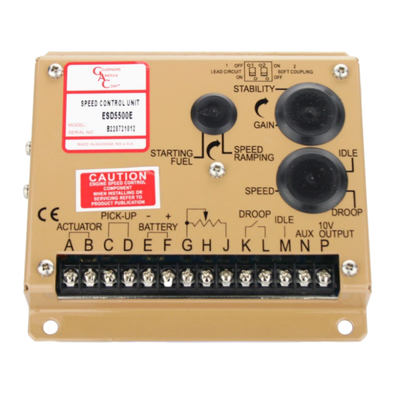
SPEED CONTROL UNIT
ESD5500E
MODEL:
S/N :
MADE IN AGAWAM, MA U.S.A.
(127)
CAUTION
ENGINE SPEED CONTROL
COMPONENT. WHEN INSTALLING
OR SERVICING REFER TO
PRODUCT PUBLICATION.
PICK-UP
ACTUATOR
A B C D E F G H J
SPEED
*
MAGNETIC
PICK-UP
_
+
S1
BATTERY
15A MAX
SEE SPECIFIC ACTUATOR PUBLICATION FOR PROPER
WIRING OF ACTUATOR BASED ON BATTERY VOLTAGE
C
ON
ORP.
STABILITY
SPEED
STARTING
RAMPING
FUEL
SPEED
-
+
DROOP
BATTERY
K
IDLE
C1 OFF
LEAD CIRCUIT
ON
DROOP
CW
SPEED TRIM
CONTROL - 5K
FUSE
6
Governors America Corp. © 2020 Copyright All Rights Reserved
OFF
E3
E2
GAIN
E1
IDLE
DROOP
IDLE
10V
AUX
OUTPUT
L M N P
ON
C2
ACCESSORY POWER
SOFT COUPLING
SUPPLY
OFF
ACCESSORY INPUT
SPEED
ADD JUMPER FOR 12V
BATTERY OR ACTUATOR
CURRENTS ABOVE 5A
GROUND REFERENCE
CLOSE FOR DROOP
CLOSE FOR IDLE
2750 Hz x 60 seconds = 1500 RPM
110 Teeth
ESD5500E Series Speed Control Unit 9-2020-F PIB1002
DEAD TIME
COMPENSATION
JUMPER
SWITCH
PROFILE
Ø0.266
(6,6)
WD554
IDLE
LEA
DROOP