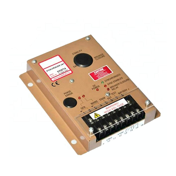
GAC SYC6714 Краткое руководство по эксплуатации - Страница 6
Просмотреть онлайн или скачать pdf Краткое руководство по эксплуатации для Оборудование для звукозаписи GAC SYC6714. GAC SYC6714 6 страниц.

6
trOUBLeSHOOtinG
The following troubleshooting steps are helpful if initial setup is not working as desired. Please contact your
any questions.
SySTEM fAIlS TO OPERATE or SyNChRONIZES POORly
STEP
ChECKS
1.
Measure the battery voltage between Terminals 8 (+) and 10 (-) . It should be 12 or 24 V DC nominal.
2.
Note the RED DC POWER LED. Measure the internal 10 V DC supply between Terminals 12 (+) and 10 (-). It should be 9.6
– 10.4 V DC.
3.
Note the RED GEN LED. Measure the AC Voltage between Terminals 1 and 2. It should be 50 - 500 V AC.
4.
Note the RED MAINS LED. Measure the AC Voltage between Terminals 3 and 4. It should be 50 - 500 V AC
5.
Note the RED SYNC ENABLE LED. Check (ON/OFF) switch (at Terminals 5 and 6) and auxiliary contacts (Parallel Cable +/-
). Measure the DC voltage between Terminals 5 (+) and 10 (-). It must be greater than 8 V DC. (See Wiring Diagram)
6.
Check the DC voltage between Terminals 7 (+) and 10 (-). This should be 10 V DC when in phase. Check the Test switch
position. It must be opened to synchronize.
7.
Also check the enable signal from the voltage matching unit if used.
8.
Measure the internal Phase Error Voltage, between Terminals 11 (+) and 10 (-). These reading should be as follows:
• If in phase, 5.1 V DC
• If less than 5.1 V DC, the generator frequency is higher than the mains frequency. Decrease the speed controller speed until
the system is synchronized.
• If greater than 5.1 V DC, the generator frequency is lower than the mains frequency. Increase the speed controller speed
until the system is synchronized.
9.
Measure the synchronizers output analog voltage between Terminals 6 (+) and 10 (-). If the generator frequency is lower than
mains, the voltage should be lower than 5.1 V DC and visa versa. Adjust the speed controller speed until 5.1 V DC is mea-
sured between Terminals 6 and 10.
10.
If the GREEN SYNCHRONIZED LED does not light, the breaker closure angle may be set too narrow. Adjust the BREAKER
ANGLE control CCW until the GREEN LED lights.
11.
If the GREEN SYNCHRONIZED LED lights continuously but the internal breaker closure relay fails to close, go back to step
6 (relay inhibited).
12.
If the unit synchronizes but does not close the breaker, check that the normally open contacts at Terminal 13 and 14 have
closed. If not, the synchronizer is defective.
fAIlURE TO SyNChRONIZE or SlOw SyNChRONIZATION
1.
The problem is usually caused by the governor system performance not being tightly controlled. The governor system perfor-
mance must be excellent to obtain fast, consistent synchronization. Controlling the phase of the generator is a more demand-
ing operation than basic speed control.
Review and optimize the governor system before attempting to service the synchronizer. Other issues may lie within the
engine and how well it is operating.
2.
Severe harmonic distortion of the AC wave from the power converters can disturb the synchronizer. If the wave form has more
than 10% distortion, or other wave form issues are suspected,
contact GAC
for an external AC filter recommendation.
6
Governors America Corp. © 2021 Copyright All Rights Reserved
GAC representative
with
SYC6714 03-2021-B2
PIB4030
