GAF Master Flow EGV5 Руководство по установке - Страница 3
Просмотреть онлайн или скачать pdf Руководство по установке для Вентилятор GAF Master Flow EGV5. GAF Master Flow EGV5 7 страниц. Power attic vent – gable mount
Note: See Figures on previous page.
1. Ensure Proper Intake Ventilation... Always
ensure there is proper intake ventilation at the sof-
it, undereave, and fascia areas of the roof. This is
required for a balanced ventilation system and to help
avoid premature ventilator motor failure. Use the chart
located on the outside of the package to ensure the
minimum recommended intake ventilation is installed
on the home. Always consult local building codes for
ventilation requirements.
2. Determine Position... Place Power Gable Vent
behind an existing gable wall louver or install a
Master Flow
SGM20 Automatic Gable Louver
®
(not included). The fan should be approximately
3" (76 mm) to 4" (102 mm) away from the
exterior louver.
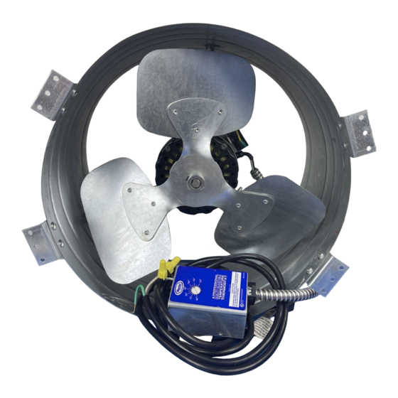
3. Attach Mounting Brackets To Unit... Carefully
remove unit and mounting accessories kit from the car-
ton. The fan mounting kit includes (8) bolts, (8) Nylok
nuts, and (4) mounting brackets. Take the mounting
brackets (long side) and align with the two holes on
the shroud. With holes aligned, take two bolts with the
head on the inside of the shroud and push through
each hole. Take the Nylok
bolt. Repeat this process until all four mounting brack-
ets are irmly fastened to shroud (Figures 1a & 1b).
4. Mount The Unit... Place mounting brackets so end
is lush with the stud. For studs 16" (40.6 cm) on cen-
ter, mounting brackets are predrilled to this size. Screw
or nail unit to framing through pre-punched holes in
Figure 3
POWER SOURCE
WHITE
GREEN
BLACK
™
nuts and fasten to each
™
GREEN
BLACK
BLACK
Installation Instructions
For Gable-Mount Models: PG2, PG3,
EGV5 & EGV6
mounting brackets (Figure 2a). For studs over 16" (406
mm) on center, install two nominal 2" x 4" (50 mm x
100 mm) wood supports, 14" (35.6 cm) apart. Mount
the unit to the two nominal 2" x 4" (50 mm x 100 mm)
wood supports through the pre-punched holes in the
mounting brackets (Figure 2b).
5. Wiring... Always disconnect power supply before
wiring the ventilator into an existing circuit. Remove
the thermostat cover and mount the thermostat box
to the edge of an adjacent rafter or stud using the
pre-punched holes. Make sure the thermostat element
opening on the back of the box isn't covered. Each
ventilator must have its own thermostat. Leave the
lexible conduit with some slack and begin wiring
the thermostat as shown (Figure 3). The included
thermostat is adjustable from 60°F (15.5°C) to 120°F
(48.8°C). The factory/recommended setting for
eficient operation is 105°F (40.5°C).
Note: In the unlikely event that accessories or parts
are missing or this product does not operate correctly,
please contact Master Flow
1-800-211-9612. Do NOT return this ventilator to
retailers or distributors.
WHITE
MOTOR
BLACK
Technical Services at
®
gaf.com