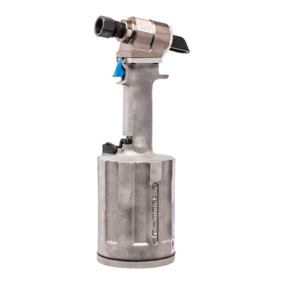
Gage Bilt GB756 Руководство - Страница 6
Просмотреть онлайн или скачать pdf Руководство для Инструменты Gage Bilt GB756. Gage Bilt GB756 14 страниц.

FILLING AND BLEEDING INSTRUCTIONS
NOTE:
704153 Air Bleeder Ass'y is required.
NOTE:
To replace a small amount of fluid start at step 7 below.
WARNING:
DO NOT CYCLE TOOL WITHOUT AIR BLEEDER, OR THE SCREW AND STAT-O-SEAL, INSTALLED IN TOOL
HEAD. SEVERE PERSONAL INJURY MAY RESULT.
CAUTION:
BEFORE FILLING HANDLE, AIR PISTON ASS'Y SHOULD BE ALL THE WAY DOWN.
CAUTION:
WHEN FORCING PISTON ROD ASSEMBLY DOWNWARD WITH HEAD CYLINDER ASSEMBLY REMOVED,
HYDRAULIC FLUID WILL EJECT FORCIBLY FROM HANDLE.
Use
CAUTION
WARNING:
Failure to follow these instructions carefully may result in severe personal injury.
WARNING:
IMPORTANT:
Be sure to use thread sealant on all hydraulic fittings, Loctite® 30534 or similar Teflon® infused pipe
dope is recommended.
however, pieces may enter the hydraulic system and cause malfunctions and damage. Use 1 1/2 wraps of
tape on each thread. Cut off all loose tape ends. Tighten until fitting feels snug and then go 1/2 to a full
turn past that point.
To replace a small amount of oil in the tool start at step 7 below.
Should it become necessary to completely refill the tool (as would be required after tool has been dismantled and reas-
sembled), take the following steps.
1. Ensure the air piston ass'y (756121) is at the full bottom of its stroke, by pushing the piston rod assembly (756134)
down until it stops.
2. Fill the power cylinder (756227) to top and oil passage to the bottom of counterbore, this should be done with gland
(756126) removed.
3. Place gland (756126) into top of handle (756229) being careful not to tear o'rings when installing.
4. Push piston ass'y (756211) in head cylinder (756300) to its full forward position (see 'A' dimension fig. A).
5. Install gasket (756148) and head cylinder (756300) onto top of handle (756229) being careful not to tear o'rings on
head cylinder (756300) or gland (756126).
6. Install the four screws (402479) into the head cylinder (756300) and tighten evenly to 40 inch lbs.
7. Make sure air supply is disconnected. Make sure piston ass'y (756211) is in its full forward position (dimension 'A'),
then remove front bleeder screw (402482) and seal (A-1155) from bleeder hole #1 (See fig. B.) on head cylinder
(756300).
8. Make sure the rear screw (402482) and seal (A-1115) are installed in the head cylinder (756300) hole marked #2, and
screw is torqued to (35-40) inch pounds.
9. Attach air bleeder ass'y (704153) to front of hole in head cylinder (756300) hole marked #1.
10. Set air supply to 40-50 psi (2.8-3.4 bar), connect air supply to the tool. Cycle tool 10 times, while holding actuator
(756142) down for 5 seconds, and releasing the actuator (756142) for 5 seconds.
11. Release the actuator (756142) and let the piston ass'y (756211) return to full forward (Dim.A). Disconnect air supply
and remove air bleeder ass'y (704153)
12. Install button head screw (402482) and stat-o-seal (A-1115) in head cylinder ass'y (756300) hole marked #1 and
torque to 35-40 inch pounds.
13. Once both button head screws (402482) and stat-o-seals (A-1115) are installed in the head cylinder (756300) holes
marked #1 and #2 , and torqued to 35-40 inch pounds, connect the air supply (40-50 psi. or 2.8-3.4 bar).
14. Hold the actuator (756142) down for 3 to 5 seconds and disconnect the air supply. The piston ass'y (756211) should
be at (Dim. B).
15. Remove the rear button head screw (402482) and stat-o-seal (A-1115) from the head cylinder (756300) hole marked
#2. Attach the air bleeder ass'y (704153) to the rear hold marked #2.
16. With the front button head screw (402482) and stat-o-seal (A-1115) installed and the air bleeder ass'y (704153) in-
stalled in hole marked #2, connect the air supply (40-50 psi. or 2.8-3.4 bar) and cycle the tool 10 times.
17. Hold the actuator (756142) down for 3 to 5 seconds and disconnect the air supply. The piston ass'y (756211) should
be at (Dim. B).
18. Remove air bleeder ass'y (704153), install rear button head screw (402482) and stat-o-seal (A-1115) in head cylinder
ass'y (756300) marked #2 and torque to 35-40 inch pounds.
19. Once both button head screws (402482) and stat-o-seals (A-1115) are installed in the head cylinder (756300) holes
marked #1 and #2 , and torqued to 35-40 inch pounds, connect the air supply (40-50 psi. or 2.8-3.4 bar).
20. The piston ass'y (756211) should move full forward to (Dim. A). Cycle the tool 10-20 times, checking the stroke (Dim.
A) and (Dime B). If stroke checks ok the bleeding procedure is complete.
21. If Dim. A checks long and piston ass'y (756211) does not come completely full forward, disconnect air supply then
remove both front and rear button head screws (402482) and stat-o-seals (A-1115) from holes marked #1 and #2 and
push piston ass'y (756211) full forward until it stops (Dim. A) and repeat bleeding procedure beginning at step #8.
22. If Dim. B checks short, disconnect air supply, remove both front and rear button head screws (402482) and stat-o-
seals (A-1115) from holes marked #1 and #2 and push piston ass'y (756211) to the rear (Dim. B). Replace rear button
head screw (402482) and stat-o-seal (A-1115) in rear hold marked #2 and repeat steps 9-20.
S/N: 1226 AND ABOVE
PLEASE CONTACT GAGE BILT FOR ALL OTHER SERIAL NUMBERS.
when removing screws and air bottle assy. hydraulic fluid may be under pressure.
CAUTION:
Teflon® tape is an excellent thread sealer. If it is not properly applied,
CAUTION:
Over tightening can easily distort the threads.
6
REV. 3/14
