Gage Bilt GB910 Краткое руководство по эксплуатации - Страница 6
Просмотреть онлайн или скачать pdf Краткое руководство по эксплуатации для Инструменты Gage Bilt GB910. Gage Bilt GB910 13 страниц. Hydraulic powerunit

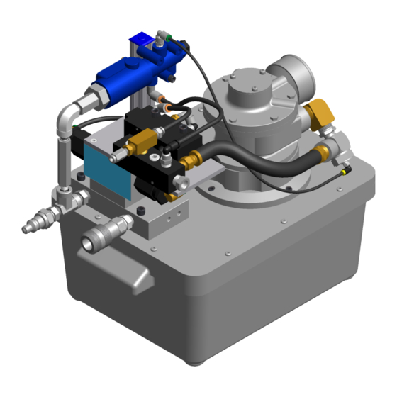
The GB910 Powerunit should be checked, as required by the installation tool manual, at first time start-up,
when troubleshooting and after overhauling directional valve or pump. For assisting in this procedure use
Pressure Checking Gauge Set-Up 942280.
TO CHECK PULL PRESSURE
1. Disconnect tool from GB910 power unit
2. Connect valve #1 of pressure gage to pull side of GB910 power unit
3. Open valve #1 (counter clockwise) and close valve #2 (clockwise)
4. Plug the air trigger from the installation tool into power unit.
5. Cycle tool to start the motor and directing hydraulic fluid to pull side of power unit. And read gage
pressure.
CAUTION:
THE GB910 POWERUNIT IS DESIGNED FOR HIGH PRESSURES FOR ONLY A SHORT
PERIOD. COMPLETE THIS CHECK AS QUICKLY AS POSSIBLE.
TO CHECK RETURN PRESSURE
1. Disconnect tool from GB910 power unit
2. Connect valve #2 of pressure gage to return side of GB910 power unit
3. Open valve #2 (counter clockwise) and close valve #1 (clockwise)
4. Plug the air trigger from the installation tool into power unit.
5. Cycle tool to start the motor, release trigger directing hydraulic fluid to return side of power unit and read
gage pressure.
SETTING OR ADJUSTING OUTPUT PRESSURES
PULL Pressure Procedure: (See page 10 for adjusting screw location.)
1. Turn adjusting screw in to increase PULL pressure.
2. Turn adjusting screw out to decrease PULL pressure.
RETURN Pressure Procedure:
1. Loosen 2 screws on name plate on top of return pressure switch.
2. Swivel name plate to the side.
3. Use 2 pin punch's to loosen lock washer.
4. Tighten or loosen adjusting nut against spring to increase or decrease return pressure. Tightening or
compressing spring will increase return pressure. Once pressure is set tighten lock nut against adjusting
nut.
6
REV. 10/13
