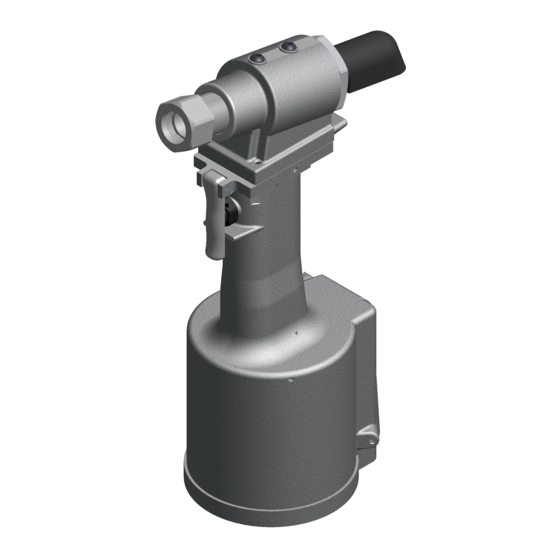
Gage Bilt GB730 Руководство пользователя - Страница 8
Просмотреть онлайн или скачать pdf Руководство пользователя для Электроинструмент Gage Bilt GB730. Gage Bilt GB730 13 страниц. Installation tool
Также для Gage Bilt GB730: Руководство по установке (14 страниц)

TROUBLESHOOTING
Providing all maintenance conditions have been met, follow this systematic approach to diagnosis.
1. MORE THAN ONE PULL IS REQUIRED TO BREAK RIVET.
a)
Tool needs to be bled. (See filling and bleeding instructions.)
b)
Spring has fatigued, replace.
c)
Jaws are stripped or packed with chips. Clean or replace.
d)
Incorrect nose tip.
2. SLOW OR PARTIAL OPERATION WHEN THE TRIGGER IS DEPRESSED
a)
Head Piston Rings (A1044) and (401113) could be worn or damaged. Replace.
b)
Piston Rod Rings (S945) and (401102) could be worn or damaged. Replace.
c)
Muffler (704146) or filter inside spool (703142) may be plugged with dirt. Clean thoroughly and back-blow with
compressed air.
d)
Hole in metering screw in valve spool (703142) may be blocked or damaged. Hole diameter should be .028". Clear and
size or replace.
3. NO OPERATION WHEN TRIGGER IS DEPRESSED
a)
Tool seized due to mechanical failure or damaged parts.
4. OIL LEAKAGE
a)
DO NOT
OPERATE WITH OIL LEAKING FROM TOOL. HIGH PRESSURE OIL MAY CAUSE SEVERE PERSONAL INJURY.
b) Any oil leaking externally should be traced to its source. An o'ring or seal that leaks should be replaced.
5. AIR BYPASS FROM VALVE HOUSING
a)
If the spring (704141) breaks or dislodges, air will flow freely through the muffler (704146). Replace or reset. Valve spring
installation tool (704162) is recommended.
b)
Check o'rings on valve sleeve (703139), valve spool (703142), and valve plug (704145). If worn or damaged, replace.
Valve sleeve removal tool (704163) is recommended.
6. FASTENER STEM JAMMED IN NOSE ASSEMBLY
a)
Nose assembly components require service.
disassemble. Replace worn or broken parts. Clean the surface the jaws ride on.
b)
Stems lodged side by side in the follower. Disassemble, remove stems, and reassemble.
c)
Incorrect follower.
OVERHAUL
The disassembly and re-assembly procedure can be accomplished by utilizing the following instructions and drawings. Use extreme
care during disassembly and re-assembly not to mar or nick any smooth surface that comes in contact with seals. Before installing
seals, always apply a good lubricant, such as Lubriplate®, to the surfaces. It is recommended that tool kit (GB730TK) be used to
facilitate overhaul. A complete overhaul can be achieved by the use of Service Kit 730006 which contains a complete set of o'rings,
back-up rings, screws, washers and gasket. It is recommended that this service kit be kept available for spare parts.
WARNING
DEPRESS TRIGGER AND DISCONNECT FROM AIR WITH HEAD PISTON IN THE REAR POSITION BEFORE OVERHAUL. SEVERE
PERSONAL INJURY MAY OCCUR IF AIR HOSE IS NOT DISCONNECTED.
DOWNWARD WITH HEAD CYLINDER ASSEMBLY REMOVED, HYDRAULIC FLUID WILL EJECT FORCIBLY FROM HANDLE.
704214
STEM CATCHER BAG
PISTON ROD WRENCH
GB730TK Service Tool Kit Includes:
Part No.
Description
730151
Piston Rod Wrench
704150
Packing Plug Wrench Assembly
704151
Power Cylinder Tool
704152
Seal Guide
745163
Fill Bottle Assembly (Not Shown)
S1178
Valve Extractor (Not Shown)
704162
Valve Spring Installation Tool (Not Shown)
704163
Valve Sleeve Removal Tool (Not Shown)
DISCONNECT AIR FROM
704151
POWER CYLINDER TOOL
730151
PACKING PLUG WRENCH
USE CAUTION
8
TOOL, remove the nose from the tool and
704152
SEAL GUIDE
704150
WHEN FORCING PISTON ROD ASSEMBLY
Rev. 9/11
