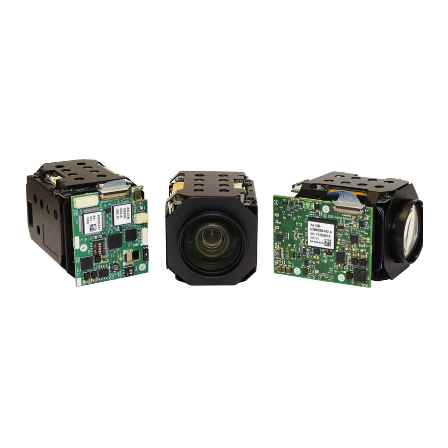
Active Silicon HARRIER Краткое руководство по эксплуатации - Страница 11
Просмотреть онлайн или скачать pdf Краткое руководство по эксплуатации для Оборудование для звукозаписи Active Silicon HARRIER. Active Silicon HARRIER 15 страниц. Usb/hdmi camera interface board

Figure 16. Selecting the Harrier USB/HDMI Camera Interface Board for display
Once the video has started in the default video mode, you can then select a different video mode
(see Figure 17). The video modes supported/listed will depend on the camera connected.
Once the video mode has been selected the HarrierView Application will change the camera mode
with a UVC command and will then capture USB video from the Harrier USB/HDMI Camera Interface
Board / camera in that format. Note: DIP switch SW1 [7] must be set to ON.
Figure 17. Selecting a camera video mode in the HarrierView application
Note: If the video mode is then changed using VISCA control, the HarrierView Application may not
be able to capture the video. The actual video mode of the camera output can be easily determined
by checking the format of the HDMI output of the Harrier USB/HDMI Camera Interface Board or by
using a VISCA inquiry. If the output from the HDMI interface and the mode selected in the
HarrierView Application are the same please check the interface board LED for error conditions and
ensure that you have a USB Type C cable of the correct specification (USB3.X Type A/C to Type C,
SuperSpeed, minimum 5 Gbps). If there is a USB video error the LED will flash red and the USB and
HDMI video outputs will be disabled.
You can use the other controls in HarrierView to record video and (if the video view window is larger
than the resolution of the video from the camera) enlarge the video to fit the view window.
March 2021
HARRIER USB/HDMI CAMERA INTERFACE BOARD
QUICK START GUIDE
Version 1.7 – March 2021
Page 11 of 14
