Hi-Link HLK-LD015-5G Руководство пользователя - Страница 6
Просмотреть онлайн или скачать pdf Руководство пользователя для Блок управления Hi-Link HLK-LD015-5G. Hi-Link HLK-LD015-5G 8 страниц. Radar module
HLK-LD015-5G
User Manual
Add Serial port
or I/O port
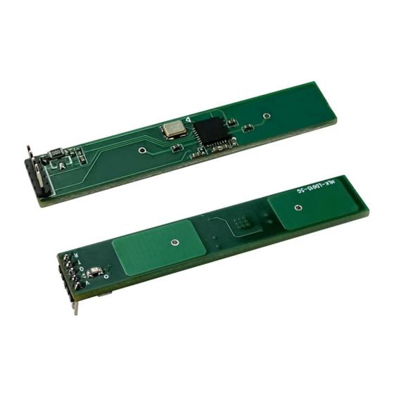
Figure 3. PIN Foot of Parameter Adjustment
7. Photosensitive detection
The module supports photosensitive detection, but photosensitivity can be optional. If
photosensitive function is required, a photosensitive diode and regulation resistor can be added to
the position shown in Figure 4. The photosensitive detection function should also be enabled in the
software. The photosensitive threshold can be adjusted by the regulation resistor. In the version
with photosensitive function, the radar sensor will be activated only when the ambient light is lower
than the set illuminance. If the light is too bright, the module will not activate the sensor function.
When testing the radar performance separately, you can cover the photosensitivity with black tape
to avoid photosensitive effect, which affects the activation of the radar sensor function.
Photosensitive diode
Figure 4. Photosensitive adjustment
8. Module power-on sequence diagram
The module has a power-on self-check function, that is, after the module is powered on, the
OUT pin first outputs a high level, and then outputs a low level after 1s delay. The low level enters
the normal induction mode after 1s delay. The following is the squence diagram of the control
signal after the module is powered on
Page 4 / 6