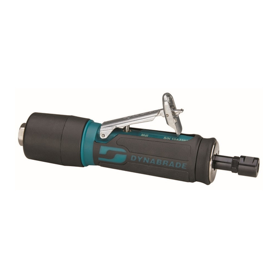
Dynabrade 48341 Руководство по безопасности, эксплуатации и техническому обслуживанию - Страница 5
Просмотреть онлайн или скачать pdf Руководство по безопасности, эксплуатации и техническому обслуживанию для Шлифовальный станок Dynabrade 48341. Dynabrade 48341 9 страниц. .4 hp die grinder ergo-grip - rear exhaust

Disassembly/Assembly Instructions
Important: The Dynabrade Pneumatic Power Tool Lifetime Warranty Policy does NOT cover normally wearable parts and products. Before servicing this tool
please contact Dynabrade Inc. or a Dynabrade Subsidiary for information regarding the Dynabrade Pneumatic Power Tool Lifetime Warranty Policy.
Notice: To avoid damaging the motor housing, use the Special Repair Tool that is designed for disassembly and assembly of these die grinders.
See page 8 for a complete list of available repair tools.
Disconnect the die grinder from the air supply.
Motor Disassembly:
1. Secure the air inlet adapter of the die grinder in a vise with aluminum or bronze jaws so that the collet assembly is pointing up.
2. Loosen the collet cap and remove the insert tool, cap and insert.
3. Use the 50971 Lock Ring Tool to remove the rear exhaust cover. Turn counterclockwise.
Note: One of two things will occur.
A. The rear exhaust cover will loosen. If this occurs, remove the rear exhaust cover and remove the air motor assembly by pulling the motor out of the
housing. Remove the filter cage and filter. Insert the hex end of the 96402 Special Repair Tool into the hex socket in the bottom of the housing.
Use an adjustable wrench to loosen the housing from the air inlet adapter.
96402 - Special Repair Tool
"Tear-Drop End"
B. The air inlet adapter will loosen. If this occurs, remove the air inlet adapter and valve components.
Remove the 2 valve seals (Fig.1). Insert the "Tear-Drop End" of the 96402 Special Repair Tool into the air inlet of the housing. Place the hex end of the
special repair tool in a vise with aluminum or bronze jaws so that the housing is pointing up (Fig.2 & 3). Use the 50971 Lock Ring Tool to remove the rear
exhaust cover (Fig.4). Turn counterclockwise.
FOR MODELS WITH GOVERNORS: 48201, 48203, 48325, 48327, 48341, 48345, 48360, 48365 and 48370
4. Carefully secure the wrench flats of the collet body in a vise with aluminum or bronze jaws so that the governor assembly is pointing up. Use a slot blade
screwdriver to remove the governor. LEFT HAND THREAD: Turn clockwise. Note: The governor assembly is not serviceable. If a governor fails it must be
replaced as a complete assembly.
FOR ALL MODELS:
5. Fasten the 96346 Bearing Separator (2") around the portion of the 01476 Cylinder that is closest to the 02673 Rear Bearing Plate. Place the bearing
separator and the motor in the 96232 Arbor Press (#2) so that the collet body is pointing down.
6. Use a 5/32" (4 mm) diameter flat end drive punch as a press tool to push the rotor out of the 02696 Bearing.
7. Remove the cylinder and vanes.
8. Use the 5/32" (4 mm) diameter flat end drive punch to push the 02696 Bearing out of the 02673 Rear Bearing Plate.
9. Secure the body of the rotor in a vise with aluminum or bronze jaws and remove the 01435 Collet Body. Turn counterclockwise.
10. Remove the 01478 Front Bearing Plate, 02649 Bearing, shims, and 01479 Spacer.
Motor Disassembly Complete.
Important: Clean and Inspect Parts for Wear or Damage Before Assembling.
Hex End
1
(continued on next page)
2
5
3
4
