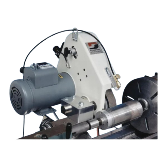
Dynabrade 65750 Руководство по эксплуатации - Страница 5
Просмотреть онлайн или скачать pdf Руководство по эксплуатации для Шлифовальный станок Dynabrade 65750. Dynabrade 65750 7 страниц. 2" wide x 48" long abrasive belt machine
Также для Dynabrade 65750: Руководство по эксплуатации (7 страниц)

Coolant Nozzle:
The coolant nozzle can be extended or retracted (if dia. allows) for good placement of coolant flow by loosening hex
screw (P/N 95179). Retighten once placement is achieved. The coolant nozzle has an adjustable flow valve which
connects to 1/4" diameter flexible nylon tubing.
Drip Pan:
The drip pan is hinged on a #10 eye screw and can be tilted fore and aft to direct coolant toward lathe bed.
Catch Tray Assembly:
Each machine comes equipped with an adjustable catch tray which positions underneath the contact wheel. Its
purpose is to collect the major portion of grind dust/swarf and direct it away from the lathe ways. It should be placed
within 1/8" of workpiece. Position can be changed by loosening knob (P/N 97773). When grinding into a shoulder, it
will be necessary to remove tray entirely.
The grinders described in this manual have been designed to be maintenance-free. All bearings and moving parts
are sealed/shielded and lubricated for life. Electric motor maintenance should be performed as recommended by the
motor manufacturer.
Good housekeeping is essential to insuring long life of any machine tool. By keeping the machine clean and visually
inspected for any wear, the machine will provide many years of quality service.
Periodically inspect the contact wheels, idler rolls and drive pulley for any signs of wear. Repairing or replacing worn
parts early enough will prevent other parts from becoming damaged.
M
A
ACHINE
DJUSTMENTS
Belt Change/Installation:
1. Remove Belt Guard by grasping door latch
(P/N 97760) and rotate 1/4 turn counter-clockwise.
2. Turn off air supply at valve (item #42). This will retract air
cylinder (item #35) and thus removes tension from the belt.
3. Remove and replace belt.
4. Important: With hands clear from moving parts, turn air supply
back on at item #42. Regulator pressure should be set to 90 PSI
for proper belt tensioning.
5. "Jog" motor by turning on momentarily to ensure proper belt
tracking. Tracking procedure is described below.
Replace belt guard and turn door latch 1/4 turn clockwise until
"click" is heard.
Belt Tracking:
Belt tracking is accomplished by turning the tracking knob (P/N
95314). Turning clockwise moves belt to the right. Turning
counter-clockwise moves belt to the left.
M
AINTENANCE
6
