Hi-Velocity RBM-50 Руководство по установке - Страница 7
Просмотреть онлайн или скачать pdf Руководство по установке для Блок управления Hi-Velocity RBM-50. Hi-Velocity RBM-50 12 страниц. Rbm refrigerant base module
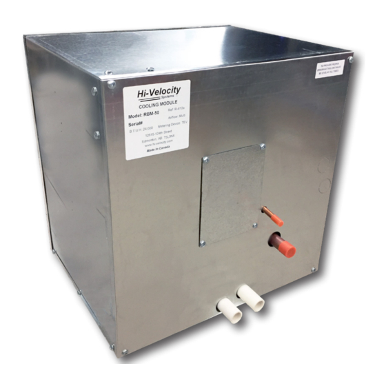
Piping the RBM
Only refrigerant grade pipe and fittings are to be used with
the RBM Module. Plumbing fittings may contain wax or other
contaminants which are detrimental to the proper operation of
the system. Insulate the suction line with a minumum of 3/8"
insulation. In high heat areas, a minimum of 1/2" insulation may
be needed. If the lines are run in an area where temperatures
could exceed 120°F or runs longer than 50', then the liquid line
may need to be insulated as well. Support the pipe every 5 feet,
or whatever local code states.
Run the pipes in the most direct route possible, taking into
account structural integrity, building details and local building
codes. If the evaporator is located above the condenser, slope
any horizontal runs toward the condenser. If the condenser is
located above the evaporator, a P-trap must be installed at the
bottom of the vertical riser. For long vertical risers, additional
P-traps must be installed for every twenty feet. For lines running
over 50', a suction line accumulator must be installed. Lines
running over 100' are not recommended.
Pipe Sizing
Tables 01 and 02 contain line sizing information for the liquid
and suction lines.
Table 01 – Liquid Line sizes
Distance
1
1
⁄
1
2
1'–25'
⁄
⁄
1
1
5
4
4
26'–50'
⁄
⁄
5
5
3
16
16
51'–75'
⁄
⁄
3
3
3
8
8
76'–100'
⁄
⁄
3
3
1
8
8
Table 02 – Suction Line sizes
Distance
1
1
⁄
2
1
2
1'–25'
⁄
⁄
5
5
3
8
8
26'–50'
⁄
⁄
5
3
3
8
4
51'–75'
⁄
⁄
3
3
7
4
4
76'–100'
⁄
⁄
3
7
7
4
8
The sizes given in the above tables are only for general reference, if the
condenser manufacture requires a different size than specified in Table 01
and Table 02, their sizing shall be used whenever a discrepancy occurs.
Outdoor Unit Installation
Locate the outdoor unit in a suitable location, as close as
possible to the fan coil. Maintain the clearances recommended
by the manufacturers of the outdoor unit, to ensure proper
airflow. The outdoor unit must be installed level, in a properly
supported location. A liquid line filter/drier is recommended to
be installed.
Tons
2
2
⁄
3
3
⁄
4
1
1
2
2
⁄
⁄
⁄
⁄
⁄
3
3
3
3
16
8
8
8
8
⁄
⁄
⁄
⁄
⁄
3
1
1
1
8
8
2
2
2
⁄
⁄
⁄
⁄
⁄
1
1
1
1
8
2
2
2
2
⁄
⁄
⁄
⁄
⁄
1
1
1
1
2
2
2
2
2
Tons
2
⁄
3
3
⁄
4
1
1
2
2
⁄
⁄
⁄
⁄
⁄
3
3
7
7
4
4
4
8
8
⁄
⁄
⁄
⁄
1
⁄
3
7
7
1
4
4
8
8
8
⁄
⁄
1
⁄
1
⁄
1
⁄
7
1
1
1
8
8
8
8
8
⁄
1
⁄
1
⁄
1
⁄
1
⁄
1
1
1
1
8
8
8
8
8
www.hi-velocity.com
Wiring – Outdoor Unit
Make all connections to the outdoor unit with rain tight
conduit and fittings. Most building codes require a rain tight
disconnect switch at the outdoor unit as well (always check
local codes). Run the proper size copper wires to the unit, and
connect as per the manufacturer's recommendations.
Ensure that the unit is setup for a TX system. If not, a hard
start kit may be required.
The system must be brazed under a nitrogen purge to
prevent oxidation of the pipe during the brazing process. After
the piping is installed and all components have been brazed
together, a vacuum pump must be used to properly evacuate
the system from both of the access ports to 1500 microns, to
ensure system is free of contaminants. Add refrigerant to the
system to bring the pressure above zero psig. After allowing
the refrigerant to absorb moisture, repeat the above procedure.
Evacuate the system to 500 microns on the second evacuation,
and ensure that the system holds at the vacuum pressure. If not,
check for leaks and evacuate again. If the vacuum holds, add
refrigerant to raise the pressure to 2 psig. At this point open
service valves on pre-charged condensing units.
The use of an electronic leak detector is recommended, as it is
more sensitive to small leaks under the low pressures.
5
⁄
1
Once the system has been determined clean and ready for
2
charging, refrigerant can be added. The service valves on the
⁄
1
2
condenser must be open at this point. Never leave the system
⁄
1
unattended when charging. With the system running, slowly
2
add refrigerant. The typical operating point of an RBM coil is
⁄
1
2
that of a saturated suction temperature of 34-40°F at 100-115
psig (1-4°C at 7-8 bar) and a suction line temperature of 38-
44°F at 114-128 psig (3-7°C at 8-9 bar). In order to prevent
overcharging during this stage, refrigerant should be added in
5
steps. This will allow time for the system to settle and prevent
'overshooting' the ideal charge. Condenser pressures and
1
temperatures remain similar to those in a conventional forced
1
⁄
1
air system. It is recommended that the coil be charged on a
8
high load day at the compressor's highest speed.
1
⁄
1
8
Most system start ups require only an adjustment to the
1
⁄
1
8
refrigerant level of the system. Should further refinement
be required, the TXV may be adjusted. A clockwise turn of
the superheat adjustment stem (the direction in which the
cap is screwed on) will result in a closing of the valve while a
counterclockwise turn (the direction in which the cap was
unscrewed) will result in opening of the valve. Always note
system conditions before adjusting the valve and allow 5 minutes
for the system to settle before making any further adjustments.
Never adjust the TXV more than one quarter turn at a time.
Important:
evacuating and charging procedures may
void warranty.
-7-
-7-
Module RBM
RBM Refrigerant Base Module Installation
Evacuating
Charging
Failure to follow the proper
© 1995-2020 Energy Saving Products Ltd.
© 1995-2020 Energy Saving Products Ltd.