DYNACO PAT-4 Руководство по сборке - Страница 14
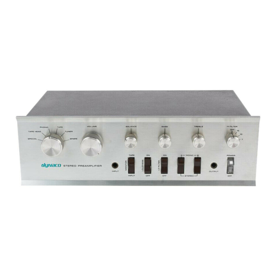
Просмотреть онлайн или скачать pdf Руководство по сборке для Усилитель DYNACO PAT-4. DYNACO PAT-4 20 страниц. Power supply
Также для DYNACO PAT-4: Руководство по сборке (16 страниц)
4. Carefully loosen the set screws in all the knobs. Remove the knobs and store them
in a safe place.
5. Remove the retaining nuts on the control shafts which hold the front panel to the
sub-chassis.
6. Remove the front panel and set it aside in a safe place.
7. Remove the nut that retains the HI FILTER switch.
Removing the HI FILTER switch.
The switch is held in by 6 wires:
2 black ground wires
2 green wires that carry left channel output signals
2 red wires that carry right channel output signals
To remove the HI FILTER switch:
1. Cut the 6 wires near where they enter the HI FILTER switch.
2. Coil the two black wires, leaving them out of the way; near, but not making
electrical contact to, the bottom of the chassis.
3. splice the two green wires together.
4. splice the two red wires together.
Mounting the tone control switch
1. Prior to installing the tone control switch, carefully bend the locator tab flat using
small pliers.
2. Remove both nuts from the shaft of the switch but leave the washer in place. One
of the nuts fastens the switch to bare chassis. The other nut will hold the front
panel to the chassis in final assembly.
3. Install the tone control switch through the front panel from the inside of the
chassis, making sure that the ALPHA stamped portion of the switch faces up.
4. Slide one of the retaining nuts over the switch shaft and tighten it, making sure
that the switch is vertical. You can check the orientation by temporarily installing
the knob from the HI FILTER switch on the shaft of the tone control switch. The
set screw should make contact with the flat side of the D-shaped shaft.
5. Turn the knob counterclockwise. The indicator line should be at 12 o'clock if the
switch has been installed straight up and down.
Wiring in the tone control switch
1. Desolder the wire that connects to the right channel circuit board eyelet 17. The
right channel circuit board is closest to the front of the preamp. I've found the best
way to do this is:
a. Heat the solder side of the eyelet 17 connection. When the solder flows,
pull the wire out with needle nose pliers.
b. Get a toothpick ready to insert into eyelet 17 from the component side.
Heat the solder side of eyelet 17 again, and push and turn the toothpick
into the hole from the component side of eyelet 17. This clears the hole for
later insertion of a new wire.
Page 14 of 20