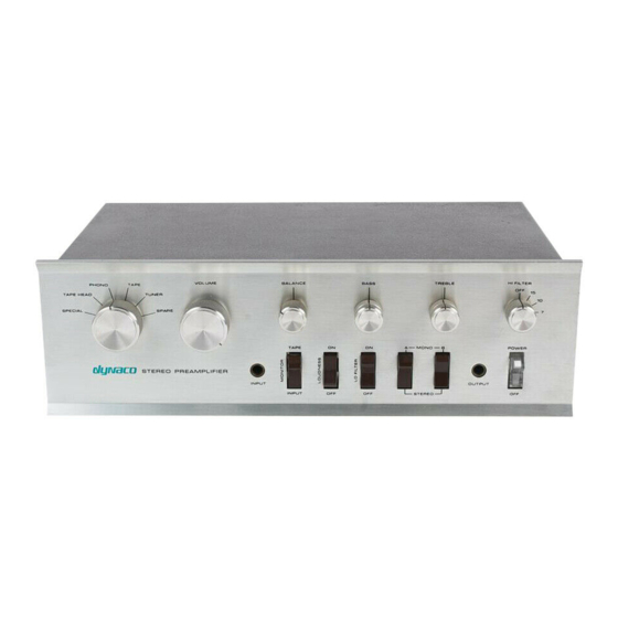
DYNACO PAT-4 Руководство по сборке - Страница 17
Просмотреть онлайн или скачать pdf Руководство по сборке для Усилитель DYNACO PAT-4. DYNACO PAT-4 20 страниц. Power supply
Также для DYNACO PAT-4: Руководство по сборке (16 страниц)

Replace the cover on the chassis, and re-insert the 4 screws that hold the cover in
place.
Using the Tone Control Switch
If you have followed the directions, the OFF position of the HI FILTER switch turns off
the tone controls. The 15 position of the HI FILTER switch turns the tone controls on. If
you have not installed gain changing resistors, then going between the OFF and 15
positions has the effect of removing the tone control action without changing the gain.
The 10 and 7 positions of the high filter switch are not available after the modification is
completed.
Pops and Clicks
There should be no pops or clicks when switching between the on and off position. If
there's a loud pop, and if it gets worse with more bass boost, then you'll probably find
that C16 has become leaky. Another sign of a leaky C16 is a scratchy bass control, even
after it has been cleaned.
It's probably best to just replace C16, but there's an interesting leakage test you can
perform:
1. Work safely, disconnecting the PAT-4 from power before working on it.
2. Desolder the negative end of C16.
3. Connect the desoldered negative end of C16 to the positive lead of a DC micro-
ammeter. Connect the negative lead of the meter to ground.
4. Remaining clear of the exposed 120 Volts, plug the PAT-4 in and power it up.
5. Observe the DC micro-ammeter. As the capacitor charges at first, there will be
significant charging current. After a few seconds, it should subside to zero.
6. Note that 0.02 mA (20 uA) is definitely not zero! A typical bad capacitor will
have that much leakage. A good capacitor should have much less than 1 uA of
leakage current.
C16 is originally 50 µF, but 47 µF is an equally fine replacement. It should have a
working voltage rating of greater than or equal to 25 Volts.
Why does C16 become leaky? It sits right above R20, a 620 Ohm, 1 Watt resistor that
dissipates about 640 mW. In most of examples I've seen, C16 actually touches R20. The
heat is probably the cause of the failure. Replacement caps typically have a bit smaller
diameter, putting some space between themselves and R20. This should enhance the life
of the new cap.
Finally, it's probably a good idea to replace C16 in both left and right channels.
If there's a click, re-check the solder joints on the 4.7 MegOhm resistors added to eyelets
16, 17, and 18, as shown in Figure 6.
Page 17 of 20
