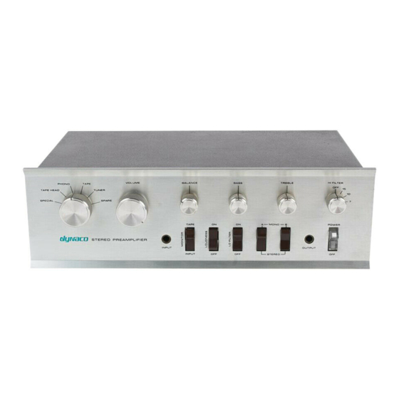
DYNACO PAT-4 Руководство по сборке - Страница 9
Просмотреть онлайн или скачать pdf Руководство по сборке для Усилитель DYNACO PAT-4. DYNACO PAT-4 20 страниц. Power supply
Также для DYNACO PAT-4: Руководство по сборке (16 страниц)

Modifying the Right Channel Circuit board
Now it's time for a second judgment call. You probably have enough access to the right
channel PCB that you can remove Q4, the metal transistor with the clip-on heat-sink,
with no further disassembly. You can even replace Q4 with the supplied TO-92 transistor
and heat sink with no further disassembly. If however, you are uncomfortable with this,
the following directions may help.
4. Remove the 4 screws that hold the right channel circuit board into the U-shaped
bracket. This should give you enough freedom of motion with the circuit board
that changing Q4 can be fairly easy.
5. To Remove Q4:
a. Slip off the clip-on heat-sink.
b. Desolder each of the three leads in turn.
c. Remove the transistor
6. Preparing for the new Q4 (Figure 1, right channel):
a. Taking each of the three leads in turn, heat the pads on the PCB into which
Q4 was installed. Run a toothpick into the accompanying eyelet from the
component side of the board. This will clear the hole, allowing the new
Q4's leads to be installed.
b. Smear a film of thermal compound onto the T0-92 transistor and insert a
heat sink over its body. Be careful to keep heat sink compound off the
leads.
c. Insert the leads of the MPSW45A transistor into the space for Q4,
matching emitter, base, and collector to the indicated places. Note that the
emitter of the transistor goes toward the bottom of the PCB (away from
the eyelets).
d. Solder the three leads of the new transistor in place.
Inspection and Reassembly
Inspect your work for good solder joints and freedom from solder bridges. Assuming that
is satisfactory:
1. Reassemble the PCB's to the U-shaped retaining bracket.
2. Solder the numbered wires into the numbered eyelets on the PCBs. Make sure not
to mix left and right channel wires up.
3. Re-fasten the u-shaped brackets to the bottom of the chassis.
4. Reinstall the cover using the 4 screws (2 on each side) that hold it in place.
5. You're ready to listen to music with lower distortion.
Page 9 of 20
