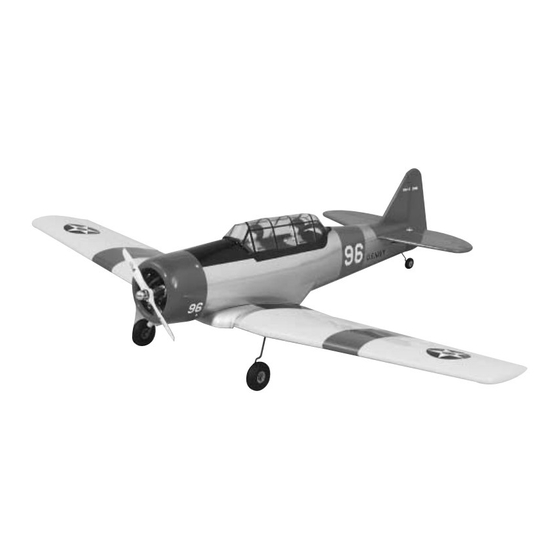
GREAT PLANES AT-6 Texan Руководство по эксплуатации - Страница 14
Просмотреть онлайн или скачать pdf Руководство по эксплуатации для Игрушка GREAT PLANES AT-6 Texan. GREAT PLANES AT-6 Texan 20 страниц. Legendary warbirds custom-wood series

Note: Throws are measured at the widest part of the
elevators, rudder and ailerons. If your radio does not have
dual rates, set the control throws to halfway between the
specified high and low rates. We recommend the following
control surface throws as a starting point.
High Rates
Elevator
1/2" up, 1/2" down
(13mm up, 13mm down) (6mm up, 6mm down)
Ailerons11/16" up, 11/16' down
(17mm up, 17mm down) (11mm up, 11mm down)
Rudder 1-1/8" right, 1-1/8" left
(28mm right, 28mm left) (16mm right, 16mm left)
One leading cause of crashes is flying an airplane with its
control throws set differently from those recommended in the
instructions. The Great Planes AccuThrow
lets you quickly and easily measure actual throws first, so
you can make necessary corrections before you fly. Large,
no-slip rubber feet provide a firm grip on covered surfaces
without denting or marring the finish. Spring tension holds
AccuThrow's plastic ruler steady by each control surface.
Curved to match control motions, the ruler provides exact
readings in both standard or metric measurements.
Route the antenna to the tail of the model. You may use
your preferred method or the method we use in the Great
Planes model shop. Drill a 1/4" (6mm) hole through the fuse
side in the proximity of the receiver. Cut a 1/2" (13mm) long
piece of fuel tubing and install it in the hole. Install a strain
relief then, route the antenna through the fuel tubing to the
bottom of the fuse at the tail. Use a rubber band to attach
the antenna to the tail gear wire. Do not cut or shorten the
antenna wire. Leave any excess to hang free.
4-CHANNEL RADIO SET-UP
(STANDARD MODE 2)
ELEVATOR MOVES UP
4-CHANNEL
TRANSMITTER
RIGHT AILERON MOVES UP
LEFT AILERON MOVES DOWN
4-CHANNEL
TRANSMITTER
RUDDER MOVES RIGHT
4-CHANNEL
TRANSMITTER
CARBURETOR WIDE OPEN
4-CHANNEL
TRANSMITTER
Low Rates
1/4" up, 1/4" down
7/16" up, 7/16" down
5/8" right, 5/8" left
(GPMR2405)
™
Make sure the
control
surfaces
move in the proper
direction as shown
in the sketch.
14
WHEEL INSTALLATION
Fixed Gear & Tail Gear
1. Remove the covering from the landing gear slot. Test
fit the Main Landing Gear. It's helpful if you use a file to
remove any burrs or sharp edges from the ends of the wire.
The gear will be swept forward toward the leading edge of
the wing. Seat the landing gear wire in the landing gear rail
on the wing. Use a Nylon Landing Gear Strap as a guide
to drill 1/16" (1.5mm) pilot holes for the screws. Secure the
landing gear with two nylon straps and four #2 x 3/8" Sheet
Metal Screws.
2. Install the main wheels using four 3/16" Wheel
Collars and 6-32 Set Screws. Grind or file a flat spot at the
point of set screw contact. This provides a better area for
the set screw to bite and helps keep the wheel in place.
Trim off any excess axle wire after installing the wheel
collar.
3. Repeat step 2 for the tail wheel. Use a 3/32" Wheel
Collar and a 4-40 Set Screw.
4. Check the fit of the Wing Center Section Cover. Trim
the wing if the cover is slightly larger than the opening. Glue
the cover to the wing using medium CA.
Retractable Landing Gear
Note: None of the hardware used in the retract
installation is included in the kit. All hardware must be
purchased separately.
The installation of the retracts requires a high degree of
testing and adjusting. Retract installation is only recommended
for experienced modelers.
