GREAT PLANES ElectriFly GPMM1850 Руководство - Страница 2
Просмотреть онлайн или скачать pdf Руководство для Контроллер GREAT PLANES ElectriFly GPMM1850. GREAT PLANES ElectriFly GPMM1850 4 страницы. High voltage brushless electronic speed controls
2
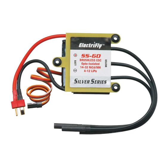
MOTOR CONNECTIONS
Each of the three motor leads is made of high-quality 12 or 14
gauge, silicone insulated wire with a gold-plated female bullet
connector on the end. These connections are not polarized,
so there is no need to match the color of the ESC and motor
wires. If the motor rotates backwards, simply switch any two
of the ESC's motor connectors. Once connected, make sure
all connections are insulated electrically. Failure to do so could
result in permanent damage to the motor/ESC, and void all
warranties.
The SS-60 includes 4mm female bullet connectors. The SS-80
includes 6mm female bullet connectors. If the connectors on
the ESC do not properly match those on the motor, an adapter
for each wire might be necessary. ElectriFly offers various
bullet connector adapters, which can be found at local retailers
as follows:
Part number Description
GPMM3114
Great Planes Gold Plated Bullet
Connector Male 4mm (3 per package)
GPMM3116
Great Planes Gold Plated Bullet
Connector Male 6mm (3 per package)
GPMM3118
4mm Male to 6mm Female Bullet
Adapter (3 per package)
GPMM3119
6mm Male to 4mm Female Bullet
Adapter (3 per package)
3
MOUNTING THE ESC
Determine the best location for the ESC, inside or outside the
fuselage.
IMPORTANT! It's highly recommended to install
the ESC so that air can freely fl ow across it during
operation! The more air which can fl ow over the ESC,
the better. This is especially important when using the maximum
number of cells on the input, when ambient temperatures are
very high, when using a lot of servos in the aircraft, or performing
very active 3D maneuvers! If the airplane's structure doesn't
naturally allow for air to fl ow into the fuselage, create vent holes
fore and aft in the fuselage to allow air to pass through and
across the ESC for cooling. Do NOT pack the ESC with foam
padding as it will not allow the ESC to properly radiate heat and
likely cause a thermal shutdown.
three #4 x 5/8" [16mm] screws with #4 washers (wood screws
for solid wood surfaces). If mounting to metal, use three 4-40
machine screws with #4 washers.
If the wires are not long enough to make all necessary
connections to the ESC yet achieve good balance in the
aircraft, it's best to extend the length of the wires to the motor
(not to the battery).
4
For proper ESC operation, it's very important to set the
transmitter's throttle channel adjustments, as follows:
5
The SS-60 and SS-80
ESCs
with
LiPo batteries. It is not
required to setup the
ESC to recognize the
exact battery type.
First, make sure the battery is FULLY charged before connecting
it to the ESC. Failure to do so will not allow the low voltage
cutoff feature to work properly (see details below). Connect the
battery to the lead on the ESC which has the Star Plug. Make
sure to observe proper polarity [red (+) leads go together, and
black (-) leads together]. NEVER allow a battery's red (+) and
black (-) wires to touch as permanent damage will result and
void all warranties!
LOW VOLTAGE CUTOFF: The SS-60 and SS-80 ESCs include
a low-voltage cutoff feature that stops motor rotation if the
battery's voltage drops too low (but power will still be supplied
to the receiver and servos so you can land the aircraft). This
protects the battery from damage. When the battery is initially
connected, the ESC measures the battery's voltage and
automatically sets the low voltage cutoff based on this initial
battery voltage multiplied by 0.74. So, if the battery is NOT fully
charged when connected to the ESC, the ESC will set a low
voltage cutoff that is too low.
Three
mounting
tabs are designed
onto the SS-60 and
SS-80 ESCs which
allows
them
to
be installed fi rmly
on
the
aircraft.
Determine
the
desired
location
6
for the ESC, and
mount fi rmly with
The SS-60 and SS-80 ESCs will cause the brushless motor to
make beeps which will aid in setting up the system. Make sure the
motor is connected, but that the propeller is removed.
BRAKE FUNCTION: The factory default brake setting is "off".
Skip to the "ESC OPERATION" section below if you want to
keep this setting. To turn the brake "on":
2
NECESSARY TRANSMITTER SETTINGS
1. Set the throttle channel's travel adjustment (ATV,EPA or
ATL) to 100%.
2. Set the throttle trim and sub-trim to neutral or zero.
3. Set the throttle channel's reversing switch to reverse on
Futaba transmitters. Other transmitters might require you
to set the throttle reversing switch to normal.
CONNECTING THE BATTERY
IMPORTANT!
FROM THE MOTOR BEFORE CONNECTING THE
BATTERY!
are
compatible
NiCd,
NiMH,
or
IMPORTANT! Make sure the battery is fully
charged prior to every use!! Failure to do so will
cause the ESC to automatically set a low-voltage
cutoff point which is too low for the battery.
ESC SETUP AND OPERATION
REMOVE
THE
PROPELLER
Star Plug
Red
Male Connector
Black
(+)
Battery Lead
(–)
ESC