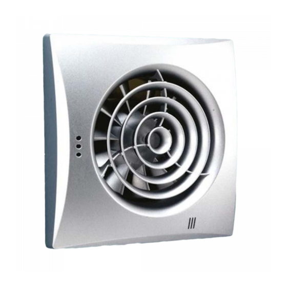
HiB 31400 Инструкции по креплению - Страница 2
Просмотреть онлайн или скачать pdf Инструкции по креплению для Вентилятор HiB 31400. HiB 31400 2 страницы. Wall mounted fans, timer/timer & humidity sensor
Также для HiB 31400: Руководство пользователя (4 страниц), Инструкции по монтажу (3 страниц)

Position the Fan into the Wall
1) Choose a suitable position for your fan
according to Figure 1 on the back page.
Use a cable fi nder to check if there are
any buried cables or pipes in the wall.
Draw around the outside of the fan
to determine its exact location with a
pencil. Mark the position of the centre of
the fan on the wall.
2) Drill a hole to mark the centre point
using a 10mm drill bit. You should
ensure that this hole is angled slightly
downwards. Using the drilled hole as a
centre point mark the extractor opening
on the outside wall.
3) Use a 10mm bit to drill a series of holes
at 35mm intervals round the edge of the
circle that was previously drawn. Use a
60mm bolster chisel and club hammer
to chop out the waste.
4) If necessary, use a chisel and hammer
to cut grooves in your internal
plasterwork to take the cable and
conduit.
5) Fit fl exible ducting (not supplied) into the
hole, fl ush with both sides of the wall.
Ensure the duct slopes slightly downwards
towards the outside. Make good any
plasterwork
around the duct.
6) Position the fan back into place, and
mark the four fi xing points. Drill the
required holes in the marked positions.
If drilling through tile, use a ceramic
drill bit. Insert wall plugs into the drilled
holes.
7) Follow a similar procedure for the
outside wall grille.
Electrical Connection
1 casing
2 retaining clip for power wires
3 holes for power wires
4 terminal block
5 holes for fan mounting
6 wire fi xing rack
1) Ensure the domestic electrical mains
supply to which the fan is being
connected is turned off. This product
is designed to be connected to an on/
off switch outside the bathroom, or to a
ceiling mounted pull cord switch.
2) Remove the protecting grille. Lead the
power supply cords through the hole (3)
which should be cut before in the plastic
casing.
3) Strip the wire leads 7-8 mm and
insert them into the terminal blocks (4)
according to the diagram below.
L is brown
LT is brown
N is blue
4) Fix the fan to the wall using 4 screws.
5) Replace the cover and protective grille.
Operating Instructions
1) For Art Nos. 31100 / 31300
Fan with timer option switches on
as control voltage is supplied to LT
terminal. After voltage is off, the fan
continues operating within the set time
period T, adjustable between 2 and 30
min. The time is regulated by turning the
potentiometer T clockwise to increase
and anticlockwise to decrease the
running-out time.
2) For Art Nos. 31200 / 31400
Fan with timer and humidity sensor
switches on as control voltage is
supplied to LT terminal or when
humidity level adjustable between 60%
and 90% is exceeded. After voltage is
off or humidity level H decreases the
fan continues operating within the set
time period adjustable between 2 and
30 min. Time T and humidity H values
are regulated by turning the appropriate
potentiometers T and H clockwise to
increase and anticlockwise to decrease
the running-out time and humidity
level respectively. To set the maximum
humidity level set the potentiometer in H
max (90%) position.
Maintenance
- Fan maintenance is to be performed
only after the fan is disconnected from
the mains power supply. Maintenance
means periodic clearing of the surfaces
from dust and dirt.
- All surfaces should be cleaned with
diluted detergent, i.e. washing up liquid,
and a soft cloth. Scourers and scouring
agents should not be used, as these
may cause damage to the surface of
the product
