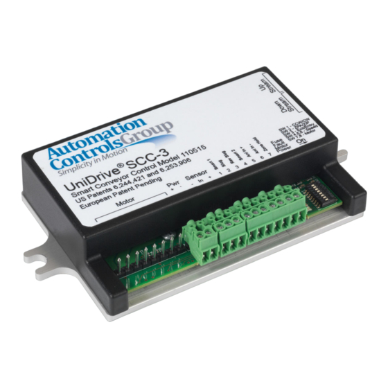
Automation Controls Group 110515 Руководство по установке и устранению неисправностей - Страница 2
Просмотреть онлайн или скачать pdf Руководство по установке и устранению неисправностей для Блок управления Automation Controls Group 110515. Automation Controls Group 110515 11 страниц. Smart conveyor control generation iii

1
2
2.1 Motor Cable & Connection Header ......................................................................................................................... 5
2.2 +24V DC Power Input Connection Header ........................................................................................................... 5
2.3 PNP Sensor Connection Header .............................................................................................................................. 5
2.4 Smart/User Input-Output Connection Header ..................................................................................................... 5
2.5 Feedback LED Indicators............................................................................................................................................ 6
2.6 Configuration Switches ............................................................................................................................................... 6
2.7 Upstream Cable Connection ..................................................................................................................................... 6
2.8 Downstream Cable Connection ............................................................................................................................... 6
2.9 Mounting Plate/Heat Sink ......................................................................................................................................... 6
2.10 Cover ................................................................................................................................................................................. 6
3
3.1 Mount the Control ......................................................................................................................................................... 7
3.2 Select a Motor ................................................................................................................................................................ 7
3.3 Select a Speed ............................................................................................................................................................... 7
3.4 Configure the Location ................................................................................................................................................ 7
3.5 Configure the Operating Mode ................................................................................................................................. 7
3.6 Configure the Rotation ................................................................................................................................................ 7
3.7 Configure Communications ....................................................................................................................................... 7
3.8 Connect User Input/Output ....................................................................................................................................... 8
3.8.1 Entry Zone ................................................................................................................................................................... 8
3.8.2 Intermediate Zone .................................................................................................................................................... 8
3.8.3 Exit Zone ...................................................................................................................................................................... 8
3.8.4 Braking & Zero Motion Hold (ZMH)..................................................................................................... 9
3.8.5 Slug & Reverse Slug Input Operation.................................................................................................. 9
3.8.6 Other Modes of Operation.....................................................................................................................9
4
4.1 Zone Hold Input........................................................................................................................................9
4.2 Configuring an SCC-3 as a BMC..............................................................................................................9
4.3 Search and Rescue ...................................................................................................................................................... 9
4.3.1 During Power Up ....................................................................................................................................................... 9
4.3.2 After Discharge of a Parcel from the Downstream Edge of a Zone..................................................9
4.3.3 After Removal of a Slug Signal..........................................................................................................10
4.3.4 After Removal of a Rev Slug Signal...................................................................................................10
5
5.1 Feedback LEDs ........................................................................................................................................................... 10
5.1.1 Fuse LED (Red)....................................................................................................................................10
5.1.2 Fault LED (Red)...................................................................................................................................10
5.1.3 Motor LED (Amber) ................................................................................................................................................ 10
5.1.4 Power LED (Green) ................................................................................................................................................ 10
5.2 Firmware Version Display ....................................................................................................................................... 10
5.3 6-Wire Modular Cable Orientation .......................................................................................................11
5.4 Additional Assistance...............,,,,,,,,,,,,,,,,,,,,,,,,,,,,,,,,,,,,,,,,,,,,,,,,,,,,,,,,,,,,,,,,,,,,,,,,,,,,,,,,,,,,,,,,,,,,,,,,,,,,,,,,,,,,,,,,,,,,,,,,11
Copyright ©2013-2018 Automation Controls Group, Inc. A division of MEC Companies, Inc. All Rights Reserved.
This document is the property of Automation Controls Group, Inc., and may not be reproduced in whole or in part without prior written approval.
Other trademarks and service marks used or referenced in this document are the property of their respective owners.
C O N T E N T S
4
5
6
9
10
