AirCycler g2-k Руководство по установке и эксплуатации - Страница 6
Просмотреть онлайн или скачать pdf Руководство по установке и эксплуатации для Вентилятор AirCycler g2-k. AirCycler g2-k 11 страниц.
Также для AirCycler g2-k: Учебное пособие (20 страниц), Руководство по монтажным испытаниям (2 страниц), Руководство по монтажным испытаниям (2 страниц)

2.1 CALCULATED FLOW SET UP
2.1.1 SETTING MEASURED SUPPLY AIR FLOW
The measured flow is the amount of air that enters the
return side of the air handler from the outside air vent.
Enter the measured flow. To accommodate variable speed
air handlers, you can enter different values for heat, cool
and fan. Factory default is 90 CFM.
Press MODE to advance to the next setting.
2.1.2 SETTING MEASURED EXHAUST AIR FLOW
Enter the measured flow from the exhaust fan. Factory default is 60 CFM.
Press MODE to advance to the next setting.
2.1.3 SETTING CODE REQUIRED CONSTANT AIR FLOW
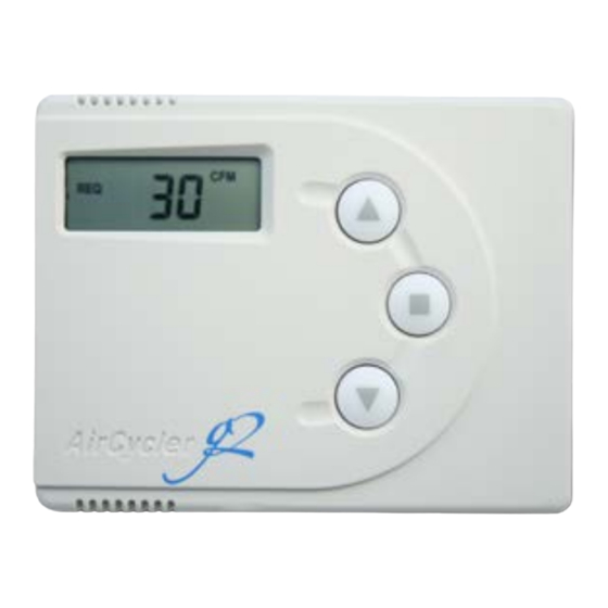
Set the required continuous air flow in CFM based on relevant codes. For ASHRAE 62.2
see Appendix A. Factory default is 30 CFM. The AirCycler® g2 will calculate run times
based on settings 2.1.1 and 2.1.2.
Press MODE to advance to the next setting
2.1.4 EXHAUST FAN DELAY TIME
Set the desired length of time you want the exhaust fan to run after the FanConnect™
switch has been turned off. Factory default is 10 minutes.
Press MODE to save all settings and return to normal operation.
2.1.5 CALCULATED FLOW SETUP IS COMPLETE
Set up is complete. The AirCycler® g2 will now return to normal operation.
Flow measured
during heat call
Flow measured during
cooling call
Flow measured during
fan only call
*Only if FanConnect™ switch is not
connected
6
Alternating
Display
Press: MODE
Alternating
Display
Press: MODE
Alternating
Display
Press: MODE
AC DOC 8.5
REV 11/21/2014
