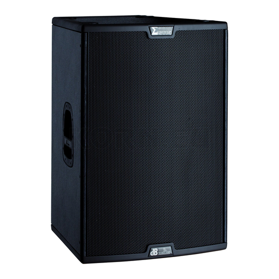
dB Technologies Sigma S118 Руководство пользователя - Страница 7
Просмотреть онлайн или скачать pdf Руководство пользователя для Динамики dB Technologies Sigma S118. dB Technologies Sigma S118 20 страниц. Sigma series professional active speaker

SIGMA S115 - SIGMA S215 - SIGMA S118
CONNECTIONS
Connecting to the mains supply
Each active speaker features its own power cable. Connection is done by a Neutrik
POWER CON® (blue) model which permits easy and fast connection to the speaker as
well as being an excellent locking system.
The same connector serves as a switch to turn ON and OFF the active loudspeaker by
turning the connector to the left (OFF) or right (ON).
The active speaker must be connected to a power supply able to deliver the maximum
required power.
Main power supply linking
On the rear of the speaker, a Neutrik POWER CON® connector (grey) offers linking the
mains power supply.
This socket links the power supply to another speaker, thereby reducing the direct
connections to the mains. Maximum amplifier input power is shown on the amplifier panel.
The maximum number of speakers connected together varies of max input power and of
the maximum allowed current of the first power socket.
CHARACTERISTICS AND PROTECTION
Front Grille
The speakers's components in the box are protected
foam on backside.
Cooling
Thermal control is provided by the internal microprocessor which, by means of two sensors,
controls the temperature of the amplifier and of the power supply, avoiding overheating by
limiting the overall volume.
In case of overheating (> 80 degrees) the volume decreases proportionally to the
temperature increase, making the change unnoticeable.
The correct volume and all the functions are automatically restored when standard
operating temperatures are reached.
Switch on
The amplifiers are equipped with a microprocessor to control the DSP and the amplifier.
The correct switch on of the amplifier is ensured by an initialization procedure; during this
test stage the LEDs ( LIMITER , SIGNAL AND READY ), located on the amplifier
"
module, remain off for approx. 2 sec.
At the end of the switch on procedure, on the amplifier module, the READY green LED
only remains steadily on.
In case of severe failure of the speaker, on the amplifier module, the LIMITER red LED
flashes. The speaker switches to "mute".
Failure indications and safeties
The microprocessor is able to signal three different kinds of failure by flashing the "LIMTER"
red LED on the amplifier panel before the lighting up of the "READY" green LED. The three
types of failure are:
1)
WARNING: a non severe error or auto-ripristinate malfunction is detected and the
performance of the speaker is not limited
2)
LIMITATION: an error is detected and the performance of the speaker is limited (the
sound level is reduced by 3dB).
This does not affect the operation of the speaker since it continues to operate.
However, it is necessary to call the service centre to solve the issue.
3)
FAILURE: a severe malfunction is detected. The speaker switches to "mute".
11
1,5mm
metal steel grille covered by
" "
"
"
"
"
"
Flashing
1 or 2
3 or 4
from 5 to 8
In case of failure, the "READY" green LED remains off.
Perform the checks listed below:
-
Check if the speaker is properly connected to the power supply.
-
Make sure that the power supply is of correct voltage.
-
Check that the amplifier is not overheated.
-
Disconnect the speaker from the mains power supply, wait for a few minutes and
connect it again.
If this error signaling remains active contact the authorized service center to resolve the
problem.
ROTATING HORN
When used horizontally, the loudspeaker allow to maintain the same coverage angle by
featuring a rotating horn.
The speakers are always supplied by the manufacturer with the horn positioned horizontal
at 60°by default.
If you wish to change the coverage angle (FIG.A page 34):
-
unscrew the fixing screws of the grille (eight screws- four for each side in S115 and
S118, twelve screws - six for each side in S215)
-
remove the front protective grille by slightly pressing on one side and taking the
grille
-
unscrew the eight fixing screws of the horn
-
rotate the horn in the desired position (the horn should never be removed from the
driver!)
-
tighten the fixing screws of the horn
-
put the grille back in the recessed slots and tighten the screws of the grille.
"
"
Indication
Warning
Limitation
Failure
off the recessed slots
12
