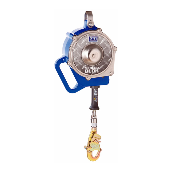
DBI SALA 3400800 Руководство пользователя - Страница 4
Просмотреть онлайн или скачать pdf Руководство пользователя для Оборудование для обеспечения безопасности DBI SALA 3400800. DBI SALA 3400800 8 страниц.

3.0
OPERaTION aND uSE
3.6
RETRIEvAL SYSTEM OPERATION: Figure 2 identifies key
components of the retrieval system. To activate retrieval mode,
rotate the locking screw down completely to free the crank arm.
Rotate the handle out from the stowed position. To engage the
winch, pull and hold the shift knob in the unlocked position. Push
the crank arm in to the engaged position and release the shift
knob. If needed, rotate the crank arm clockwise (lowering) to aid
in gear engagement.
A.
TO RAISE: Rotate the crank arm counterclockwise.
B.
TO LOwER: First crank the crank arm counterclockwise to
release the fall arrest brake, then crank clockwise.
NOTE: A minimum load of 75 lbs (33.9 kg) is required for lowering
or to pay out line. A force of up to 30 lbs is required to operate winch
when loaded to capacity.
CauTION: Stop cranking when line is fully extended or retracted.
Continued cranking can damage components.
C.
DISENGAGEMENT OF RETRIEvAL MODE: Remove any load
from the lifeline. Pull and hold the shift knob in the unlocked
position. Pull the crank arm out to the disengaged position and
release the shift knob. Secure the crank arm with the locking
screw. Pull out on the retrieval handle and rotate the handle to
the stowed position.
3.7
RETRIEvAL OvERLOAD FEATuRE: Winches on the SRL models
covered in this supplementary instruction do not incorporate an
overload clutch to limit the force applied to the drive components
and the person being raised. Care must be taken to avoid line
slack while in rescue mode. Also, the individual must be monitored
during retrieval to ensure they do not become stuck and subjected
to excessive force from continued lifting.
5.0
INSPECTION
5.6
INSPECTION STEPS FOR RETRIEvAL COMPONENTS:
Step 13. Inspect the retrieval arm for distortion or other damage.
Step 14. Ensure the locking screw can be tightened completely.
Step 15. Ensure the shift knob can be pulled out to the unlocked
Ensure that the retrieval handle can be rotated out and
secured in the cranking position.
position and then released, locking the crank arm in both
the engaged and disengaged positions.
4
