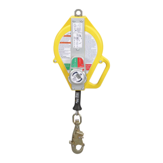
DBI SALA ULTRA-LOK 3504556C Руководство по эксплуатации - Страница 6
Просмотреть онлайн или скачать pdf Руководство по эксплуатации для Оборудование для обеспечения безопасности DBI SALA ULTRA-LOK 3504556C. DBI SALA ULTRA-LOK 3504556C 16 страниц. Self-retracting devices

3.0 INSTALLATION
3.1
PLANNING: Plan your fall protection system before starting your work. Account for all factors that may affect
your safety before, during, and after a fall. Consider all requirements and limitations defi ned in this manual.
3.2
ANCHORAGE: Figure 6 illustrates typical SRL anchorage connections. The anchorage should be directly
overhead to minimize Free Fall and Swing Fall hazards (see Section 2). Select a rigid anchorage point
capable of sustaining the static loads defi ned in Section 2.2.
3.3
HARNESS CONNECTION: A Full Body Harness is required for Fall Arrest applications. Connect the Snap
Hook on the SRL Lifeline to the Back Dorsal D-Ring on the Full Body Harness. (see Figure 7). For situations
such as ladder climbing, it may be useful to connect to the front Sternal D-Ring. Consult the harness
manufacturer's instructions for details regarding use of the harness connection points.
3.4
TRIPOD MOUNTING: Figure 8 illustrates installation of the Ultra-Lok Self-Retracting Lanyard with Retrieval
Hand-Crank on a DBI-SALA Tripod. The SRL-R is mounted on a leg of the Tripod and the Lifeline is routed
through a Pulley System on the Head of the Tripod:
1. Secure the Quick Mount Bracket on the leg of the Tripod: Assemble the Quick Mount Bracket
around the Upper Tube of the Tripod Leg. Position as desired and then tighten the mounting bolts to 15
ft-lbs (20 Nm). Do not overtighten the bolts.
IMPORTANT: Never mount the Quick Mount Bracket on the Lower (Telescoping) Tube of the Tripod
Leg.
2. Secure the SRL Mounting Bracket on the Quick Mount Bracket: Position the notches in the SRL
Mounting Bracket over the Rod Ends protruding from the Quick Mount Bracket and then pivot the SRL
toward the Tripod Leg until the holes in the SRL Mounting Bracket align with the holes in the Quick
Mount Bracket. Insert the Mounting Pin through the holes in the SRL Mounting Bracket and Quick Mount
Bracket.
3. Route the SRL Lifeline over the Tripod Head Mount Pulleys: Remove the two Retainer Pins from
the Head Mount. Position the SRL Lifeline cable in the grooves in the two Head Mount Pulleys. Reinsert
the Retainer Pins through the Head Mount.
Figure 6 – Anchorage Connections
B
C
A
B
A - Anchorage B - Connector C - Tie-Off Adapter
D - Anchorage Connector
A
D
A
B
Figure 7 – SRL Connections
A
C
E
A - Anchorage B - Anchorage Connector C - Connector
(Carabiner) D - Snap Hook E - Dorsal D-Ring
6
B
D
