Galaxy DX 44V Руководство пользователя - Страница 6
Просмотреть онлайн или скачать pdf Руководство пользователя для Трансивер Galaxy DX 44V. Galaxy DX 44V 9 страниц. Full channel am/fm mobile transceiver
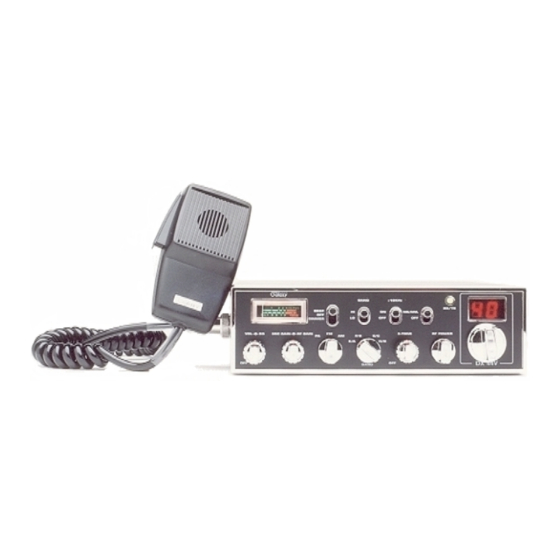
5. MODE (PA/FM/AM) SWITCH. This switch is used to select PA, FM, AM
mode of operation. The AM or FM mode is normally, but when you set to PA
position, the transceiver acts as a public address amplifier. Before operating
PA, you must first connect an external PA speaker (8 ohm, more than 2W) to
the PA Speaker jack on the unit rear panel.
6. BAND SELECTOR. This switch selects A, B, C, D, E, F, G or H band of
operation.
7. E-TONE. This control is used to echo effect and intervals of echo sound.
8. RF POWER CONTROL. Adjust this control to acquire RF power level you
desired in AM or FM transmission.
9. CHANNEL SELECTOR. This switch selects any one of the forty channels
desired. The selected channel appears on the LED readout directly above the
Channel Selector knob.
10. METER. This meter indicates received signal strength, transmitter RF output
power.
11. BEEP/DIMMER SWITCH. This switch is used to select ROGER BEEP and
lower the level of brightness of display.
12. BAND SWITCH-HI/LOW. This switch is used to select High band and or
Low band Frequency Range.
13. +10KHz FREQUENCY SHIFT SWITCH. When switch is pressed the
frequency is shifted 10KHz up. On following channels. A channel can be used
by setting this switch to +10KHz position.
Normal
3
7
11
15
19
14. OFF/ANL/NB. When the switch is placed in the ANL + NB position, the RF
noise blanker also is activated. The RF noise blanker is very effective for
repetitive impulse noise such as ignition interference.
15. RECEIVER/TRANSMIT
indicator is located next to the channel indicator. When in receive, the LED
will be green. When in transmit the LED will be red.
+10KHz
3A
7A
11A
15A
19A
INDICATOR.
The
receiver/transmit
- 9 -
16. CHANNEL INDICATOR. Numbered LED indicates the selected channel
you wish to operate on. LED indicates "9" when CH-9 is switched on.
REAR PANEL
17. POWER. Accepts 13.8V DC power cable with built-in fuse (4 amp.) to be
connected.
18. EXT SP. Accepts 4 to 8 ohms, 5 watt external speaker to be connected. When
external speaker is connected to this jack, the built-in speaker is automatically
disconnected.
19. PA. SP. Used to connect a PA speaker (8 ohm 4W) for PA operation. Before
operating PA you must first connect a PA speaker to this jack.
20. ANTENNA. Accepts 50 ohm coaxial cable with a type PL-259 plug to be
connected.
21. F.C. This socket is optional for the accessories FREQUENCY COUNTER
model FC-347, to indicate the value of the frequency ranges used.
LED
- 10 -