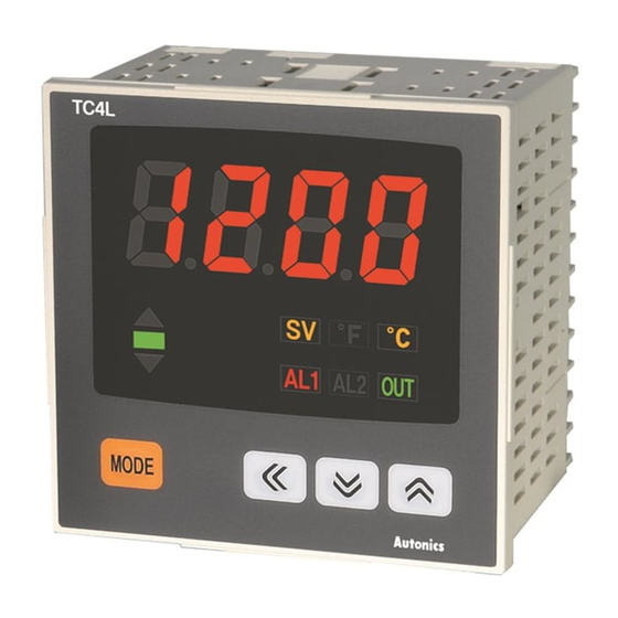
Autonics TC4L Руководство - Страница 8
Просмотреть онлайн или скачать pdf Руководство для Контроллер температуры Autonics TC4L. Autonics TC4L 14 страниц. Touch switch type temperature controller
Также для Autonics TC4L: Руководство (14 страниц), Руководство (2 страниц), Руководство по эксплуатации (2 страниц), Краткое руководство по эксплуатации (9 страниц), Краткое руководство по эксплуатации (10 страниц)

SV low-limit value
S
L-SV
SV high-limit value
S
H-SV
Control output operation
S
O-FT
Control type
S
C-MD
Control output type
S
OUT
SSR dirve output method
S
SSrM
Control cycle
S
T
AL1 alarm operation mode
S
AL-1
※ Alarm operation mode
AL2 alarm operation mode
S
AL-2
Alarm output hysteresis
S
AHYS
LBA monitoring time
S
LBaT
LBA detection band
S
LBaB
Digital input key
S
DI-K
Control output MV in case
of input break error
S
ErMV
Lock
S
LOC
Set range: Within the rated temperature range
-050
by input sensor
[ L-SV ≤ ( H-SV -1digit) ]
Set range: Within the rated temperature range
1200
by input sensor
[ H-SV ≥ ( L-SV +1digit) ]
HEAT
COOL
PID
ONOF
※ Operates only selected output between Relay or SSR.
RLY
SSR
STND
CYCL
PHAS
Set range:0.5 to 120.0 sec.
02)0
※ If control output [ OUT ] is set as RLY , factory default is 20.0 sec, or set as SSR , factory
default is 2.0 sec.
※It will not be displayed when SSR drive output mode [ SSrM ] is set as CYCL , PHAS .
AMiA
LBaA
※ Same with the above [ AL-1 ].
AM@A
Set range: 1 to 100℃/℉( DPtL / CYsL : 0.1 to 50.0℃)
00I
※ If alarm operation mod [ AL-1 , AL-2 ] of setting group 2 is set to AM)_ , SBa , LBA , AHYS
parameter is not displayed.
Set range: 0 to 9999sec. (Automatically setting with Auto-tunning)
0
※ LBaT parameter is displayed when alarm operation mode [ AL-1 , AL-2 ] of setting group 2
is set as LBA .
Set range: 0 to 999℃/℉ ( DPtL / CUs : 0.0 to 999.9℃/℉)
002
(Automatically setting with Auto-tunning)
※ When alarm operation mode [ AL-1 , AL-2 ] of setting group 2 is set as loop break alarm(LBA)
[ LBA ], and LBaT parameter does not set as 0, LBaB parameter is displayed.
※ AlRE is not displayed in case of indicator model.(TC4 -N N)
STOP
AlRE
Set range: 0.0 to 100.0%
00)0
※ 0.0/100.0% is displayed when control type parameter [ C-MD ] of setting group 2 is set ONOF .
OFF
LOC1
LOC2
Economical PID Control
※ In case of [ IN-T ] input sensor type,
low/high-limit setting temperature(SV) is
also set as max./min. temperature range
of input sensor.
※ It is displayed when selecting control output [ OUT ] as SSR .
※ AC/DC power type has no SSR dirve output method setting
function.
※ Press
AM!A
AMiB
operation mode into alarm option.
※ Refer to H-62 page.
※ Alarm option
※ For indicator model(TC4 -N N),
LOC3
only OFF , LOC1 are available.
(A)
Photo
electric
sensor
(B)
Fiber
optic
sensor
(C)
Door/Area
sensor
(D)
Proximity
sensor
(E)
Pressure
sensor
(F)
Rotary
encoder
(G)
Connector/
Socket
(H)
Temp.
controller
(I)
SSR/
Power
controller
(J)
Counter
(K)
Timer
(L)
Panel
meter
key to convert alarm
(M)
Tacho/
Speed/ Pulse
meter
(N)
Display
unit
(O)
Sensor
controller
(P)
Switching
mode power
supply
(Q)
Stepper
motor&
Driver&Controller
(R)
Graphic/
Logic
panel
(S)
Field
network
device
(T)
Software
(U)
Other
H-61
