Galaxy DX 94HP Руководство пользователя - Страница 4
Просмотреть онлайн или скачать pdf Руководство пользователя для Трансивер Galaxy DX 94HP. Galaxy DX 94HP 11 страниц. 10 meter amateur mobile transceiver with built-in frequency counter & starlite face plate
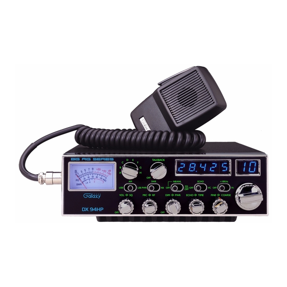
away from the microphone. In the Public Address (PA) mode, the control functions
as the volume control.
6. RF GAIN CONTROL: Adjust this knob for desired level of incoming signal.
7. DIM CONTROL: This knob controls the level of brightness for the meter lamp,
faceplate, frequency display and channel display. Turn clockwise to activate
backlight circuit.
8. RF POWER CONTROL: This control allows the user to adjust RF power output.
9. ECHO CONTROL: This control is used to adjust echo effect.
10. TIME CONTROL: This control is used to adjust intervals of echo.
11. FINE/COARSE CONTROL: Allows variation of the radio operating frequencies
above and below the channel frequency. Although this control is intended primarily
to tune in SSB signals, it may be used to optimize AM signals.
12. CHANNEL SELECTOR: This control is used to select the desired transmit and
receive channel.
13. FRONT PANEL METER: The front panel meter allows the user to monitor
incoming signal strength, RF output power and SWR level.
14. ILLUMINATED FACE PLATE: All faceplate lettering will fully illuminate to
allow the user easy viewing at night. This unique, solid state, backlight is designed
to maximize night vision while minimizing eye fatigue. Therefore, it is ideal for
both day or night.
15. BAND SELECTOR: This switch is used to select the band.
16. PWR/SWR/RB SWITCH: When in the RB position, the radio transmits an audio
tone at the end of your transmission to indicates that transmission has ended. As a
courtesy to others, use the Roger Beep only when necessary. When the switch is in
the "SWR" position, the meter indicates the Standing Wave Ratio (SWR) of your
antenna. There are no adjustments because the SWR circuit in this radio calibrates
itself automatically (accurate at maximum power output). When this switch is in
"PWR" position, the meter indicates your power output.
17. TALKBACK CONTROL: This feature is used to monitor your own voice. For
example, you could use this feature to compare different microphones. This knob
controls the volume of the Talkback level. The Talkback circuit is off when the
MIC GAIN knob is depressed.
6
18. OFF/ NB/ANL /FD.OFF SWITCH: In the NB/ANL position, the RF Noise
Blanker and the automatic Noise Limiter in the audio circuits are also activated.
The Noise Blanker is very effective in eliminating repetitive impulse noise such as
ignition interference. When the switch is in the F.D.OFF position, the frequency
Display is OFF.
19. OFF/ECHO/VC SWITCH: With the switch in VC position you can adjust the
tone and pitch of your voice. With the switch in ECHO you can add echo and
reverb to your voice. In the OFF position your voice will sound natural.
20. FREQUENCY COUNTER: This display indicates the frequency of the selected
channel.
21. OFF/+10K/PA SWITCH: When the switch is in the +10KHz position, the
frequency is shifted up 10KHz. In the PA position, the radio acts as public address
amplifier. Your voice will come out of the speaker that is plugged into the PA. SP.
jack on the rear panel. The radio does not operate when you are in the PA mode.
22. CHANNEL DISPLAY: The channel display indicates the current selected channel.
7