Galaxy DX-939 Руководство пользователя - Страница 5
Просмотреть онлайн или скачать pdf Руководство пользователя для Трансивер Galaxy DX-939. Galaxy DX-939 11 страниц. Solid state citizens band am mobile transceiver with blue illuminated lite
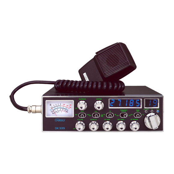
5. DIMMER CONTROL : This knob controls the level of brightness for the
meter lamp and the channel display. Also, pushing this knob turns the meter
lamp and the display LED's on and off.
6. RF POWER CONTROL : This control allows the user to adjust RF power
output.
7. CHANNEL SELECTOR : This control is used to select a desired transmit
and receive channel.
8. FRONT PANEL METER : The Front Panel Meter allows the user to monitor
signal strength, RF output power, SWR level and the AM Modulation level.
9. TALKBACK CONTROL : Pushing this knob turns the Talkback circuit on
and off. Adjust this knob for desired volume of Talkback. This is used to
monitor your own voice. For example, you could use this feature to compare
different microphones.
10. CLARIFIER : Allows tuning of the receive frequency above or below the
channel frequency by up to 1.0 KHz.
11. SWR/MOD/PWR SWITCH : This switch controls the function of the meter
during the transmit mode. In the "SWR" position, the meter indicates the
Standing Wave Ratio (SWR) of your antenna. There are no adjustments
because the SWR circuit in this radio calibrates itself automatically. When the
switch is in the "MOD" position, the green scale on the meter indicates your
percentage of modulation. When this switch is in "PWR" position, the meter
indicates your power output.
12. NB/ANL/OFF SWITCH : In the "ANL" position, the Automatic Noise
Limiter is activated. In the "NB/ANL" position, the Noise Blanker is also
activated. The Noise Blanker is very effective in eliminating repetitive impulse
noise such as ignition interference.
13. PA/CB/RB SWITCH : In the "PA" position, your voice will come out of the
speaker that you need to plug in to the "PA. SP." jack on the back of the radio.
The radio does not operate when you are in the "PA" mode. The "CB" mode is
normal operation of the radio. In the "RB" mode, you are in CB operation but
the Roger Beep is engaged. When the Roger Beep is on, the radio transmits an
audio tone at the end of your transmission. This indicates the end of your
transmission so that people who are having trouble hearing you will know that
you are done speaking. As a courtesy to others, use the Roger Beep only when
necessary.
- 8 -
14. Display ON/OFF SWITCH : When the switch is in the F.D.OFF position, the
frequency Display is OFF.
15. TONE SWITCH HI/MED/LO : This switch changes the tone quality. In LO
position, bass is increased and in HI position, treble is increased.
16. CHANNEL DISPLAY : The blue illuminated channel display indicates the
current selected channel.
17. SWR ALERT LED : This LED lights red when your SWR is higher than
about 3:1. This is not an exact indicator of 3:1 SWR, but it is an indication that
you should check your SWR reading.
18. R.B. LED : This lights green when the Roger Beep is on.
19. RX/TX LED : This LED is green during receive and red during transmit.
20. FREQUENCY COUNTER : This blue illuminated display indicates the
frequency of the selected channel.
- 9 -