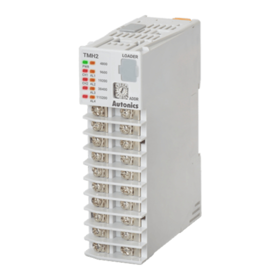
Autonics TMH Series Краткое руководство по эксплуатации - Страница 5
Просмотреть онлайн или скачать pdf Краткое руководство по эксплуатации для Контроллер температуры Autonics TMH Series. Autonics TMH Series 6 страниц. Modular2/4-channel pid temperature controllers with screw connector

TMHE [Digital input / Alarm output]
1
11
Digital1
IN
Digital2
2
12
IN
Digital3
3
13
IN
Digital4
4
14
IN
5
15
Input 1 to 4
6
16
Digital5
IN
Digital6
7
17
IN
Digital7
8
18
IN
Digital8
9
19
IN
10
20
Input 5 to 8
TMHCT [CT input]
Terminal Function
1
11
1
CT1 IN
CT5 IN
CT
CT
2
2
12
3
4
3
13
5
6
4
14
7
CT2 IN
CT6 IN
8
CT
CT
5
15
9
10
11
6
16
12
CT3 IN
CT7 IN
CT
CT
13
7
17
14
15
8
18
16
17
9
19
18
CT8 IN
CT4 IN
CT
CT
19
10
20
20
■ Communication module
TMHC-22LE [ Ladderless comm.]
Terminal RS422 RS485
RS485 (A+) RS422 R (A)
1
11
1
2
RS485 (B-) RS422 R (B)
2
12
3
4
SG
SG
3
13
5
6
RS422 T (B)
4
14
7
8
RS422 T (A)
5
15
COM1
9
10
RS485 (A+) RS422 R (A)
6
16
11
12
RS485 (B-) RS422 R (B)
7
17
13
14
SG
SG
15
8
18
16
RS422 T (B)
17
9
19
18
RS422 T (A)
19
10
20
COM2
20
Terminal
Use ring or spade terminal as below.
• Unit: mm,
≥3.0
≤5.8
Spade terminal
Terminal
Function
AL1 OUT
1
Digital input 1
2
Digital input 2
AL2 OUT
3
Input 1 to 4
Digital input 3
4
Digital input 4
AL3 OUT
5
Ground
6
Digital input 5
AL4 OUT
7
Digital input 6
8
Input 5 to 8
Digital input 7
9
Digital input 8
Alarm 1 to 4
Ground
10
11
Alarm output 1
AL5 OUT
12
Alarm output 2
13
Output 1 to 4
Alarm output 3
AL6 OUT
14
Alarm output 4
15
Ground
AL7 OUT
16
Alarm output 5
17
Alarm output 6
AL8 OUT
18
Output 5 to 8
Alarm output 7
19
Alarm output 8
Alarm 1 to 4
20
Ground
CT input 1
-
CT input 2
CT input 3
-
CT input 4
CT input 5
-
CT input 6
CT input 7
-
CT input 8
TMHC-22EE
[Ethernet comm.]
R (A)
A+
R (B)
B-
Ethernet Port 1
SG
SG
COM1
T (B)
-
T (A)
-
Ethernet Port 2
R (A)
A+
R (B)
B-
COM2
SG
SG
T (B)
-
T (A)
-
-
-
≥3.0
≤5.8
Ring terminal
Unit Descriptions
5
9
7
2
3
4
1
6
7
[Front / Side / Top]
1. Input / Output Terminal
Refer to 'Connection' for the details about terminal description.
2. Indicator
- Control module: TMH2
Status
Initial power ON
Indicator
PWR (green)
03)
LED 1 LED 2
CH1 (red)
CH2 (red)
-
(red)
(red)
(yellow)
Flash (4,800 bps)
AL1 (yellow)
Flash (9,600 bps)
AL2 (yellow)
Flash (19,200 bps)
AL3 (yellow)
Flash (38,400 bps)
AL4 (yellow)
Flash (115,200 bps) -
- Control module: TMH4
Status
Initial power ON
Indicator
PWR (green)
03)
LED 1 LED 2
CH1 (red)
CH2 (red)
-
CH3 (red)
CH4 (red)
(yellow)
Flash (4,800 bps)
(yellow)
Flash (9,600 bps)
(yellow)
Flash (19,200 bps)
(yellow)
Flash (38,400 bps)
(yellow)
Flash (115,200 bps) -
- Option module: TMHA [Analog input / output]
Status
Initial power ON
Indicator
PWR (green)
07)
LED 1 LED 2
CH1 (red)
CH2 (red)
-
CH3 (red)
CH4 (red)
(yellow)
Flash (4,800 bps)
(yellow)
Flash (9,600 bps)
(yellow)
Flash (19,200 bps)
(yellow)
Flash (38,400 bps)
(yellow)
Flash (115,200 bps) ON (CH4)
- Option module: TMHE [Digital input, Alarm output]
Status
Initial power ON
Indicator
PWR (green)
07)
LED 1 LED 2
AL1 (red)
AL2 (red)
-
AL3 (red)
AL4 (red)
(yellow)
Flash (4,800 bps)
AL5 (yellow)
Flash (9,600 bps)
AL6 (yellow)
Flash (19,200 bps)
AL7 (yellow)
Flash (38,400 bps)
AL8 (yellow)
Flash (115,200 bps) -
- Option module: TMHCT [CT input]
Status
Initial power ON
Indicator
PWR (green)
07)
LED 1 LED 2
(red)
(red)
-
(red)
(red)
(yellow)
Flash (4,800 bps)
(yellow)
Flash (9,600 bps)
(yellow)
Flash (19,200 bps)
(yellow)
Flash (38,400 bps)
(yellow)
Flash (115,200 bps) ON (10.1 to 20.0 A)
5
10
11
6
8
7
[Bottom]
Alarm output
Control
Auto
N.O.
01)
output
tuning
02)
OFF ON
ON
ON
ON
Flash
ON
Flash
-
ON
OFF
04)
ON
OFF
05)
Module communication status
-
-
OFF ON
-
-
OFF ON
-
-
OFF ON
-
OFF ON
Control output
Auto tunning
01)
ON
ON
ON
Flash
ON
Flash
ON
Flash
ON
Flash
Module communication status
-
-
-
-
-
-
-
Transmission
Internal comm.
01)
output
ON
ON
-
ON
-
ON
-
ON
-
ON
Module communication status
ON (CH1)
-
ON (CH2)
-
ON (CH3)
-
-
Alarm output
Internal
N.O.
N.C.
01)
comm.
Open
Closed Open
ON
ON
-
OFF
ON
OFF
-
OFF
ON
OFF
-
OFF
ON
OFF
-
OFF
ON
OFF
Module communication status
-
OFF
ON
OFF
-
OFF
ON
OFF
-
OFF
ON
OFF
OFF
ON
OFF
CT input
Internal comm.
01)
08)
ON
ON
ON (40.1 to 50.0 A)
-
ON (30.1 to 40.0 A)
-
ON (20.1 to 30.0 A)
-
ON (10.1 to 20.0 A)
-
Module communication status
ON (40.1 to 50.0 A)
-
ON (30.1 to 40.0 A)
-
ON (20.1 to 30.0 A)
-
-
N.C
OFF ON
06)
OFF ON
OFF ON
OFF ON
OFF ON
02)
06)
06)
Closed
ON
ON
ON
ON
06)
ON
ON
ON
ON
06)
