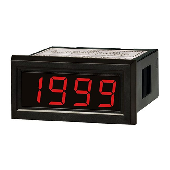
Autonics M4N-DV Series Руководство по эксплуатации - Страница 2
Просмотреть онлайн или скачать pdf Руководство по эксплуатации для Измерительные приборы Autonics M4N-DV Series. Autonics M4N-DV Series 2 страницы.

Ordering Information
This is only for reference, the actual product does not support all combinations.
For selecting the specified model, follow the Autonics webstie.
M
4
N
-
❶
-
❶ Input type
❸ Measurement input
DV: DC voltage
DA: DC current
1
DI: DC 4 - 20 mA (scaling meter)
2
❷ Power supply
3
0: 5 VDCᜡ ± 10 %
4
1: 12 - 24 VDCᜡ ± 10 %
X
Dimensions
• Unit: mm, For the detailed drawings, follow the Autonics website.
58
44
48
■ Bracket
48.6
45.2
11.6
Connections
• Socket pin no. 9, NC terminal, is not connected at inside.
• When 1 or -1 flashes with a certain measurement input, disconnect power supply and then
check the cables.
• When changing the position of the decimal point, disconnect swithcing pattern point on
PCB and change the decimal point in the external terminal socket. If changing only at the
external terminal socket not disconnecting switching pattern point on PCB, it displays both
set point: one from PCB, one from the external terminal socket.
SOURCE
[Select decimal point position]
5 VDCᜡ, 12 - 24 VDCᜡ
1
2
3
4
5
10
10
3
2
HOLD
Specifications
Model
M4N-DV-□□
Input type
DC voltage
Max. allowable input
≈ 150 % F.S. for each measured input range
Display method
7-segment (red) LED (character height: 10 mm)
Display accuracy
0.2 % F.S. rdg ± 1-digit
Sampling time
2.5 times / sec
Display scale
-1999 (4-digit)
Dual integral method
Operation method
Sampling cycle
300 ms
Response speed
≈ 2 sec (0 to 1999)
Unit weight
≈ 44 g
Approval
ᜫ
Power supply
5 VDCᜡ ± 10 % / 12 - 24 VDCᜡ ± 10 % model
Power consumption
2 W
Insulation resistance
≥ 100 MΩ (500 VDCᜡ megger)
Dielectric strength
2,000 VACᜠ 50 / 60 Hz for 1 min
Noise immunity
±100 V square wave noise (pulse width: 1 ㎲) by the noise simulator
0.75 mm double amplitude at frequency of 10 to 55 Hz (for 1
Vibration
minute) in each X, Y, Z direction for 1 hours
Vibration
0.5 mm double amplitude at frequency of 10 to 55 Hz (for 1 minute)
(malfunction)
in each X, Y, Z direction for 10 min
300 m/s
(≈ 30 G) in each X, Y, Z direction for 3 times
Shock
2
Shock (malfunction)
100 m/s
(≈ 10 G) in each X, Y, Z direction for 3 times
2
Ambient temperature
-10 to 50 ℃, storage: -20 to 60 ℃ (no freezing or condensation)
Ambient humidity
35 to 85 %RH, storage: 35 to 85 %RH (no freezing or condensation)
❷
❸
DC voltage input F.S. DC current input F.S.
199.9 mV
199.9 μA
1.999 V
1.999 mA
19.99 V
19.99 mA
199.9 V
199.9 mA
Option
Option
4
37
22
■ Panel cut-out
• Panel tickness: ≤ 10 mm
≥ 60
45
+ 0.6
0
INPUT
-
+
6
7
8
9
10
10
COM LO
HI
1
M4N-DA-□□
M4N-DI-□X
DC current
DC 4 - 20 mA
Decimal Point
The displaying decimal point is set in the product by your order. (10
10
: DOT3)
3
• DP□ pattern points on PCB are not related with the decimal point. Do not change the
soldering.
DP1
DP2
DP8
DOT3
DOT2
DOT1
Connections of Applications
■ DC voltmeter connection
• V1 (measuring voltage): ≤ 200 VDCᜡ
Hi
Power
Panel
V1
Load
meter
supply
Low
• In case of using muliple voltmeter
Voltmeter
Voltmeter
LOW
HI
LOW
+
DC
rectified
power
-
It is available using several voltmeters with providing one DC power. However, the potential
difference between - of measurement iput and - of power may cause an error.
■ DC ammeter connection
• I (measuring current): ≤ DC 200 mA
Hi
I
Panel
Power
meter
supply
Load
Low
• In case of using multiple ammeter
+
Load
power
-
HI
LOW
HI
LOW
Ammeter
Ammeter
DC power
DC power
supply 1
supply 2
Ammeter cannot be used with above connection, provide power separately.
■ Simulaneous connection of voltmeter and ammeter
+
Load
power
-
HI
LOW
HI
Voltmeter
Ammeter
DC power
DC power
supply 1
supply 2
• Connect the separated power supply each.
• (-) terminal of the power and (-) terminal of measurement input are shorted.
In case of using same power supply, measurement error or overcurrent may occur.
■ Scaling meter connection
Temperature
Sensor
OUTPUT:
CONVERTER
DC 4 - 20 mA
Pressure
(1 - 5 VDCᜡ)
Sensor
18, Bansong-ro 513Beon-gil, Haeundae-gu, Busan, Republic of Korea, 48002
www.autonics.com | +82-51-519-3232 | [email protected]
: DOT1, 10
1
10
: DOT1
1
10
: DOT2
2
10
: DOT3
3
• V1 (measuring voltage): ≥ 200 VDCᜡ
Multiplier
R1
Panel
V1
Load
V2
R2
meter
Select R1 and R2 in order to make V2 less than max.
measuring voltage using multiplier.
(R1 > R2)
R2 × V1
V2 =
R1+R2
Voltmeter
HI
LOW
HI
• I (measuring current): ≥ DC 200 mA
I
Panel
Shunt
50 mVDCᜡ
meter
Load
When the current is higher than DC 200 mA, use
shunt.
Second section of shunt is 50 mVDCᜡ.
Load
HI
LOW
Ammeter
DC power
supply n
Load
LOW
+
Hi
Panel
Power
supply
meter
Low
-
-
: DOT2,
2
Hi
Power
supply
Low
Hi
Power
supply
Low
