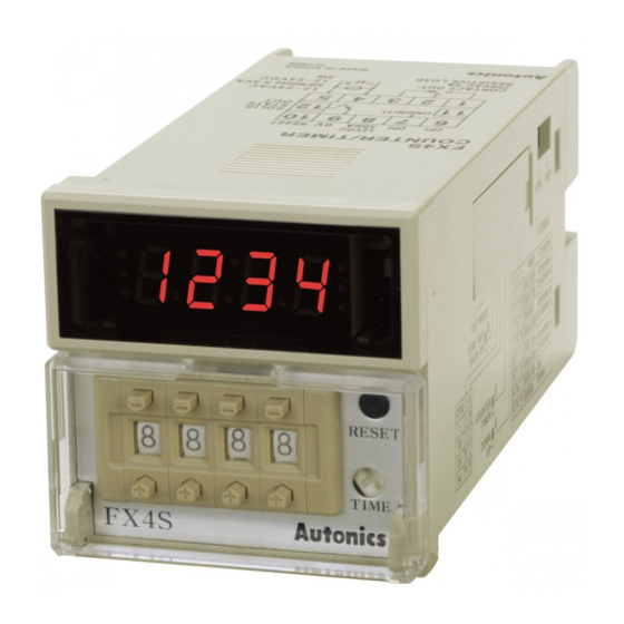
Autonics FX5S-I Руководство по эксплуатации - Страница 4
Просмотреть онлайн или скачать pdf Руководство по эксплуатации для Таймер Autonics FX5S-I. Autonics FX5S-I 5 страниц. Din w48xh48mm, preset counter/timer
Также для Autonics FX5S-I: Руководство (8 страниц)

Input Operation Mode
■ Counter
Counting chart
01)
Mode
Voltage input (PNP)
H
CP1
L
Up / Down - A
H
: command
CP2
L
input
3
2
1
0
Counting
H
CP1
L
Up / Down - B
H
: individual
CP2
L
3
input
2
1
Counting
0
H
CP1
Up / Down - C
L
4-B
: phase
H
CP2
difference
L
3
2
input
1
0
Counting
H
CP1
L
H
CP2
L
2
Up
1
0
Counting
: count up
input
H
No counting
CP1
L
A
H
CP2
L
2
1
0
Counting
H
CP1
L
A
Up / Down - D
H
: command
CP2
L
n
input
n-1
n-2
Counting
n-3
0
H
CP1
L
Up / Down - E
H
CP2
: individual
L
n
input
n-1
n-2
n-2
Counting
n-3
0
H
CP1
L
Up / Down - F
4-B
: phase
H
CP2
L
difference
n
n-1
input
n-2
Counting
n-3
0
H
CP1
L
H
CP2
L
n
n-1
n-2
Counting
Down
0
: count down
H
input
No counting
CP1
L
A
H
CP2
L
n
n-1
n-2
Counting
0
01) CP: clock pulse, n: +max. display value
A should be over min. signal width, B is over 1 / 2 of min. signal width. If the signal is smaller than these widths,
it may cause counting error (± 1).
No-voltage input (NPN)
H
CP1
L
A
A
H
CP2
L
3
3
2
2
2
1
1
0
Counting
H
CP1
L
H
CP2
L
3
3
2
2
2
1 1
1
Counting
0
H
CP1
L
4-B
H
CP2
L
3
3
2
2
2
1
1
Counting
0
H
CP1
L
A
A
H
CP2
L
No counting
5
4
3
2
1
0
Counting
H
CP1
No counting
L
A
A
H
CP2
L
5
4
3
1
Counting
0
H
CP1
L
A
H
CP2
L
n
n-1
n-1
n-2
n-2
n-2
Counting
n-3
n-3
0
H
CP1
L
H
CP2
L
n
n-1 n-1
n-1
n-2
n-2
n-2
Counting
n-3
n-3
0
H
CP1
L
4-B
H
CP2
L
n
n-1
n-1
n-2
n-2
n-2
Counting
n-3
n-3
0
H
CP1
L
A
A
H
CP2
L
n
n-1
No counting
n-2
n-3
Counting
n-4 n-5
0
H
CP1
No counting
L
A
A
H
CP2
L
n
n-1
n-2
n-3 n-4
Counting
n-5
0
Output Operation Mode
• Output type
One-shot output
• Set One-shot output time via [TIME] volume switch on the front side.
Setting range: 0.05 to 5 sec
A
A
Output operation description in input operation mode
Mode
Up, Up / Down - A, B, C
3
2
2
1
RESET
Setting
F
Output
3
2
2
1 1
After count-up, counting display value increases or decreases until RESET input is applied
and retained (hold) output is maintained.
RESET
Setting
3
2
2
N
1
Output
After count-up, counting display value and retained (hold) output are maintained until
A
A
RESET input is applied.
RESET
No counting
5
4
Setting
3
C
Output
A
When count-up, counting display value is RESET and it counts simultaneously.
5
4
RESET
3
2
Setting
R
A
A
Output
After count-up, counting display value is RESET after One-shot output time and it counts
n-1
simultaneously.
n-2
n-2
n-3
RESET
Setting
K
n-1 n-1
Output
n-2
n-3
After count-up, counting display value increases or decreases until RESET input is applied.
RESET
Setting
P
n-1
n-2
n-2
Output
n-3
After count-up, counting display value is maintained while output is ON, and internally
RESET and it counts simultaneously.
A
A
RESET
Setting
No counting
n-3
n-4 n-5
Q
Output
After count-up, counting display value increases or decreases during One-shot output
A
time.
■ Counter
n-3 n-4
n-5
Output operation description in input operation mode
Mode
Up
RESET
Setting
S
Output
Output maintains ON when counting display
value ≥ setting value.
Output operation description in input operation mode
Mode
Up / Down - A, B, C
RESET
Setting
S
Output
Output maintains ON when counting display
value ≥ setting value.
■ Timer
Output operation description in input operation mode
Mode
Up, Up / Down - A, B, C
RESET
Setting
S
Output
Output turns OFF → ON → OFF repeatedly (flicker).
Retained (hold) output
Down, Up / Down - D, E, F
RESET
Setting
0
Output
RESET
Setting
0
Output
RESET
Setting
0
Output
RESET
Setting
0
Output
RESET
Setting
0
Output
RESET
Setting
0
Output
RESET
Setting
0
Output
Down
RESET
Setting
0
Output
Output maintains ON when counting display
value ≤ setting value.
Up / Down - D, E, F
RESET
Setting
0
Output
Output maintains ON when counting display
value ≤ setting value.
Down, Up / Down - D, E, F
RESET
Setting
0
Output
0
0
0
0
0
0
0
0
0
0
