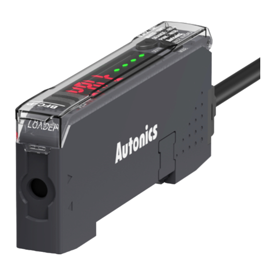
Autonics BFC Series Руководство по эксплуатации - Страница 2
Просмотреть онлайн или скачать pdf Руководство по эксплуатации для Медиаконвертер Autonics BFC Series. Autonics BFC Series 4 страницы. Fiber optic amplifier communication converters

Ordering Information
This is only for reference, the actual product does not support all combinations.
For selecting the specified model, follow the Autonics website.
BFC
-
❶
❶ Input method
N: NPN solid-state input
P: PNP solid-state input
Product Components
• Product
• Connector cable
Sold Separately
• Fiber optic amplifier: BF5 series
• Communication converter: SCM series
Software
Download the installation file and the manuals from the Autonics website.
■ DAQMaster
It is the comprehensive device management program for Autonics' products, providing
parameter setting, monitoring and data management.
Manual
For proper use of the product, refer to the manuals and be sure to follow the safety
considerations in the manuals.
Download the manuals from the Autonics website.
Connections and Circuit
■ NPN solid-state input
Serial
Phone Jack
Com
I
C
2
Side Connector
Com
12-24 VDCᜡ
■ PNP solid-state input
Serial
Phone Jack
Com
I
C
2
Side Connector
Com
12-24 VDCᜡ
• Instruction manual
• Side connector
Orange
A+
PC
RS485
&
RS485
Out
PLC
B-
Pink
3.3 VDCᜡ
Black (SW1)
3.3 VDCᜡ
SW input
White (SW2)
GND (external)
Orange
A+
PC
RS485
&
RS485
Out
PLC
B-
Pink
VCC (external)
Black (SW1)
SW input
White (SW2)
Dimensions
• Unit: mm, For the detailed drawings, follow the Autonics website.
Ø4.1
4.7
10
2
Error
Error
Cause
Data read/write error occurs in EEPROM
of the amplifier.
ERA
- Slave fails to execute the Master's
instructions such as 1:M copy, load all,
save all, and group teaching due to
ERB
unstable communication lines.
- Another communication error occurs.
Specifications
Model
BFC-□
Supported amplifier
BF5 Series
Comm. function
RS485, Serial communication, Switch (SW) input
Switch (SW) input
HIGH: 5-24 VDCᜡ, LOW: 0-1 VDCᜡ
Real-time monitoring (incident light level, output state),
Function
Executes all functions and sets the parameters of BF5 Series via
external devices (PC, PLC)
TX indicator (red), RX indicator (green),
Indicator
display screen (PV display part: red LED, SV display part: green LED)
Approval
ᜢ ᜫ
Unit weight
≈ 15 g
Power supply
12-24 VDCᜡ ±10% (using the power supply of the connected amplifier)
Current consumption
≤ 40 mA
Control output
NPN solid-state input / PNP solid-state input model
1 mm double amplitude at frequency 10 to 55 Hz (for 1 min)
Vibration
in each X, Y, Z direction for 2 hours
Shock
500 m/s
(≈ 50 G) in each X, Y, Z direction for 3 times
2
Ambient temperature
-10 to 50 ℃, storage: -20 to 60 ℃ (no freezing or condensation)
Ambient humidity
35 to 85%RH, storage: 35 to 85%RH (no freezing or condensation)
Protection rating
IP40 (IEC standard)
Connection
Connector cable
Cable spec.
Ø 4 mm, 4-wire, 2 m
Wire spec.
AWG22 (0.08 mm, 60-core), insulator outer diameter: Ø 1.25 mm
Material
Case: PBT, cover: PC
Communication Interface
■ RS485
Comm. protocol
Modbus RTU
Application standard
Compliance with EIA RS485
Max. connection
31-unit (communication address setting: 01 to 99)
Comm. synchronous method Asynchronous
Comm. method
2-wire half duplex
Comm. distance
≤ 800 m
Comm. speed
1,200 / 2,400 / 4,800 / 9,600 / 19,200 / 38,400 bps
Comm. response time
20 to 90 ms
Start bit
1-bit
Data bit
8-bit
None, Even, Odd
Parity bit
Stop bit
1-bit, 2-bit
48.4
35mm DIN rail
70
6.7
72
78.7
Troubleshooting
Check the circuitry around EEPROM
inside the product.
- Check the cascading status.
- Check the circuitry around the side
connector and hardware condition.
