Autonics BD Series Руководство - Страница 4
Просмотреть онлайн или скачать pdf Руководство для Датчики безопасности Autonics BD Series. Autonics BD Series 14 страниц. Laser displacement sensors amplifier unit
Также для Autonics BD Series: Руководство по эксплуатации (6 страниц), Руководство по эксплуатации (5 страниц), Руководство по эксплуатации (3 страниц)

-|Transparent setting
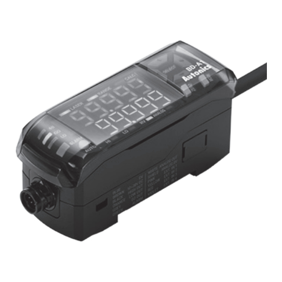
▣ Unit Description
◎ Sensor head
1
2
3
4
◎ Amplifier unit
12
3
4
5
1
Present value (PV) display: Red
Displays PV, calculating result (when using calculation),
parameter name (when setting parameter).
2
Setting value (SV) display: Green
Displays SV (HIGH, LOW, RV, Analog output, Bank),
parameter setting value (when setting parameter). The type
of displaying SV can be recognized by Setting value (SV)
indicator recognition .
3
Judgment indicator: Red (HI/LO), Green (GO)
Lights ON when outputting judgment value following to SV.
4
Alarm indicator: Red
Lights ON when outputting alarm.
5
Optimization setting key [AUTO]
Executes Sensing optimization .
6
Setting value (SV) indicator recognition lamp: Green
Displays the value type of Setting value (SV) display
HI/LOW: HIGH/LOW judgment value
RV: Real distance value
ANALOG: Analog output
guide|-
7
8
11
10
▲
1
◀
▶
▼
2
6
7
8
Laser Displacement Sensor
1
Power indicator (red)
Indicates whether power supply the sensor head.
2
Receiver
5
Receives reflected laster from the object.
3
Emitter
6
Emits laser to the object to measure the displacement.
4
Emission center line
The line and the object should be aligned because the
laser is emitted along the line.
5
Laser emission indicator (green)
Lights ON during sensor head emits laser.
6
NEAR/FAR indicator (green)
Out of the rated measurement range: Flashing
Near the reference distance: Turns ON.
7
Mounting hole
8
Connector cable
9
7
Zero adjustment setting key [ZERO]
Executes Zero adjustment .
8
Mode setting key [MODE]
Enters modes and sets the parameter value.
9
Direction key [◀/▶/▲/▼]
Sets the value of mode and parameter.
10 Calculation indicator (CALC): Green
Lights ON when using calculation.
11 Measurement range indicator (RANGE): Green
Lights ON when PV is in the measurement range, lights OFF
when PV is out of the measurement range or emitting laser
is stopped.
12 Laser emission indicator (LASER): Green
Lights ON when emitting laser.
E-9 -9
