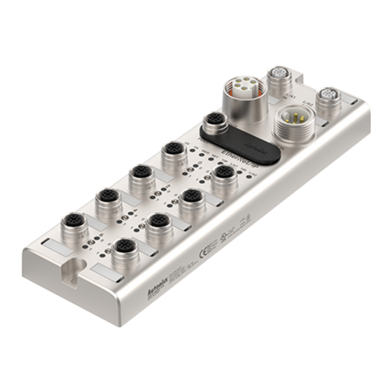
Autonics ADIO-EI Руководство по эксплуатации - Страница 6
Просмотреть онлайн или скачать pdf Руководство по эксплуатации для Системы ввода/вывода Autonics ADIO-EI. Autonics ADIO-EI 10 страниц. Remote i/o boxes (ethernet/ip)

IP Address Settings
To connect to the EtherNet/IP network, configure the EtherNet/IP interface. The IP address can be assigned using the following methods.
■ Rotary switches
Be sure to place the seal of the protective cover firmly on the rotary switches after completing the settings.
The protection rating is not guaranteed when the protective cover is open.
x100
x10
01. Rotate the rotary switches to set the mode and IP address. The green LED of the US indicator flashes.
Setting mode
Rotary switches
Default IP Address
000
Static IP Address
001 to 255
BOOTP
800 to 899
DHCP
900 to 999
02. Turn on the ADIO-EI again.
03. Check that green LED of the US indicator is ON.
04. The IP address has been changed.
05. Put the protective cover on the rotary switches.
■ atIOLink
The address assigned by the atIOLink software is stored in the ADIO-EI's EEPROM. For more information, refer to the atIOLink User Manual.
Address
Description
Static IP Address
The default IP address of the ADIO-EI
Subnet Mask
The subnet mask of the IP network
Gateway Address
The IP address of the gateway
x1
Description
This IP address is stored in the ADIO-EI's EEPROM.
Applying the IP address set on the atIOLink software.
The IP address of the Ethernet port. Set the last octet of the IP address.
The IP address is assigned by the Bootstrap Protocol (BOOTP)-server.
The IP address is assigned by the DHCP-server.
Factory settings
192.168.2.3
255.255.255.0
192.168.2.1
Value
Factory settings: 192.168.2.3
192.168.2.□□□
IP Address, Subnet Mask., etc
IP Address, Subnet Mask., etc
