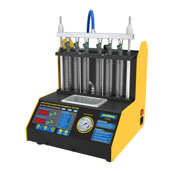
Autool CT-200 Руководство пользователя - Страница 8
Просмотреть онлайн или скачать pdf Руководство пользователя для Оборудование для уборки Autool CT-200. Autool CT-200 14 страниц. Injector cleaner & tester
Также для Autool CT-200: Руководство (18 страниц), Руководство пользователя (14 страниц)

Up-inlet injector installation method and testing steps
Select the oil separator from the accessory box, select
the matching "O" ring and install it on the blockage, and
apply a little grease to load the plug into the oil separator.
Install the crescent-shaped pressure plate and tighten the
platen screws.
According to the type of nozzle connection, select the
appropriate straight oil connector to be installed at the
corresponding coupler under the oil separator.
Install the injector in the forward direction (apply a small
amount of grease on the "O" ring of the injector).
According to the height of the injector, select the
appropriate adjusting screw and knurled nut to install on
the oil separator bracket. Then install the oil separator
and fuel injector on the oil separator bracket and evenly
tighten the two knurled screws (black). The installation
diagram is shown in Figure.03.
Insert the injector pulse signal line.
If there is a test solution in the test cup, press the
[Oil drain] button to drain the test solution from the test
cup.
Select the uniformity/atomization detection in the control
panel, set the corresponding working condition parameters,
and press the [Run] key
(Note:During operation, press the [Oil drain] key to perform
uniformity and atomization. Switching between each other).
13
After
the
test
is
completed,
automatically and beep with a buzzer.
1-Platen
screw;
2-Knurling
screw; 3-Moon tooth plate; 4-Oil
separator is blocked; 5-Straight
oil connector; 6-Top fuel supply
nozzle; 7-Knurled nut;
8-Adjustment screw
Side- inlet injector installation method and testing steps
Select the appropriate side oil supply nozzle from the
accessory box (select the appropriate "O" ring on the
coupling and apply a little on the "O" ring of the coupling
and injector) Grease).
Insert the injector into the coupling and load it into the oil
separator together.
Install the cross platen and tighten the platen screws.
Install the oil separator and fuel injector on the oil separator
bracket
and
evenly
tighten
(black).The installation diagram is shown in Figure.04.
Insert the injector pulse signal line.
If there is a test solution in the test cup, press the
[Oil drain] button to drain the test solution from the test
cup.
the
system
will
stop
Figure.03
the
two
knurled
screws
14
