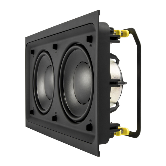
Dynaudio S4-LCR65W Руководство по установке - Страница 7
Просмотреть онлайн или скачать pdf Руководство по установке для Динамики Dynaudio S4-LCR65W. Dynaudio S4-LCR65W 9 страниц. Studio series. s4-lcr series

Diagram 6: S4-LCRMT and twin S4-LCR65W connection in passive mode.
Crossover assembly screws
+
–
Jumpers in J1 position
Switch in 2W position
4.2 Active Mode
• In active mode, each S4-LCRMT and single or multiple S4-
LCR65W module employed for each channel is connected
separately to a power amplifier channel.
• The mode selection switches on the rear of each S4-LCR65W
module or modules should be switched to "BYP" (bypass).
Ensure that the mode selection switch position is correct
before use.
• The two mode selection jumpers on the crossover PCB of
each S4-LCR65W module should be located in the J2 position.
The mode selection jumpers can be accessed by lifting the
crossover PCB module from the back of the S4-LCR65W
module. This is achieved by removing the four screws identified
in Diagram 7.
• The power amplifier channel driving each S4-LCRMT and
S4-LCR65W modules must be driven via active filters. The
recommended filter characteristics are tabulated below.
Connect to amplifier
–
Crossover assembly screws
+
IMPORTANT
Ensure that the mode
selection switch
position is correct.
Damage may result if
the switch position is
Jumpers in J1 position
incorrect.
Filter
S4-LCR65W
S4-LCRMT
Type
Low pass
High pass
Frequency
300 Hz
500 Hz
Slope
12 dB/octave
12 dB/octave
Q
0.71
1.0
Gain
0 dB (see note)
0 dB
Note: Where a S4-LCRMT module is used with a single S4-
LCR65W module ,the S4-LCR65W gain should be reduced by
-6 dB.
Diagram 7: S4-LCRMT and single S4-LCR65W connection in active mode.
Crossover assembly screws
Connect to bass amplifier
+
–
Jumpers in J2 position
Switch in BYP position
Diagram 8: S4-LCRMT and twin S4-LCR65W connection in active mode.
Connect to bass amplifier
Crossover assembly screws
+
–
Jumpers in J2 position
Switch in BYP position
Connect to mid/tweeter
–
amplifier
+
IMPORTANT
Ensure that the mode selection switch
position is correct. Damage may result
if the switch position is incorrect.
Connect to mid/tweeter amplifier
Connect to bass amplifier
–
Crossover assembly
+
+
screws
–
IMPORTANT
Ensure that the mode
selection switch
position is correct.
Damage may result if
Jumpers in J2 position
the switch position is
incorrect.
