Emerson Enardo EN-FVFA-2412 Руководство по эксплуатации - Страница 3
Просмотреть онлайн или скачать pdf Руководство по эксплуатации для Промышленное оборудование Emerson Enardo EN-FVFA-2412. Emerson Enardo EN-FVFA-2412 8 страниц. Free vent flame arrestor

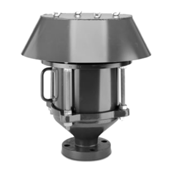
Figure 3. Free Vent Flame Arrestor
INFORMATION
DEF
L
/D = n/a
u
BC: b
Ex. G IIA
T
o
P
o
Principle of Operation
The Free Vent Flame Arrestors prevent flame propagation by
absorbing and dissipating heat using spiral wound crimped ribbon
flame cells. These cells allow maximum flow with maximum
protection. The Free Vent Flame Arrestor is used to stop the
propagation of confined and unconfined low pressure deflagrations.
It prevents an ignited atmospheric vapor cloud from propagating
beyond the flame arrestor into the vent line or tank.
Free Vent Flame Arrestors allow free venting and flame protection
for vertical vent applications. Designed with flanged connections,
this arrestor allows removal of the flame cell element without their
removal of the venting assembly.
Factors Affecting Flame
Arrestor Performance
Gas Group
The type of gas in the system determines its gas grouping and
therefore predetermines the type of arrestor element required.
The element must be designed to accommodate the specific gas
group that could possibly ignite and propagate in the system. The
more explosive gases require the flame cell to absorb the heat
more quickly and efficiently. The International Electrotechnical
Commission (IEC) groups gases and vapors into Groups IIA through
IIC categories depending on a number of factors including the
Maximum Experimental Safe Gap (MESG) of the gas.
Maximum Initial Operating Pressure
The Free Vent Flame Arrestor is intended to operate at atmospheric
pressure when at or near static flow conditions.
Flame Arrestors have installation and application limits
Type designation in accordance with EN ISO-16852:2010
DEF
Table 2. Marking Plate Information (See Figure 4)
Indicates product is a Deflagration Flame Arrestor
The ratio of pipe length (between the potential ignition source and the flame arrestor) and pipe diameter.
Indicates end-of-line configuration. Prevents unconfined deflagration from entering a tank or enclosure
Indicates the flame arrestor is for short-time burning, not to exceed 1 minute
Indicates the arrestor is rated for use in Explosion Group IIA vapors
Indicates maximum operational temperature of flame arrestor
Indicates maximum operational pressure of flame arrestor
Burn Time Rating
All Enardo EN FVFA Series flame arrestors are rated for short time
burning with a temperature sensor in place. If no temperature sensor
is installed, this product is not suitable for short time burning.
Installation
Connection
Enardo flame arrestors are normally provided with CL150 raised or
flat face flanges. Other flange patterns including DIN patterns are
available upon request. Make sure the companion flange installed in
adjacent piping matches the flange on the flame arrestor. For proper
bolt torquing of the flame arrestor flange to the piping, please refer
to Tables 4, 5 and 6.
Free Vent Flame Arrestor
WARNING
/D = n/a
= 1 min
L
BC: b; t
u
BT
Ex. G IIA
T
= 60°C
o
MARKING PLATE (SEE TABLE 2)
HAZARDOUS LOCATIONS
Figure 4. Product Identification and Marking
DESCRIPTION
CAUTION
Temperature sensors must be used with this
product. The response time of the sensor must be
at least as fast as that of a Type K thermocouple
in a stainless steel sheath. The tip of the sensor
should be installed such that it is within 5 inches /
125 mm of the face of the element assembly. Never
disconnect or remove these devices.
WARNING
!
Verify that the flame arrestor being installed has the
appropriate gas group rating for your process. This
information is shown on the nameplate attached
to the element housing. Do not remove or alter
this nameplate.
Always make sure that the system is at atmospheric
pressure and there is no ignitable gas that could flash
when either installing or maintaining the unit.
P
= 0.10 MPa (absolute)
o
3
