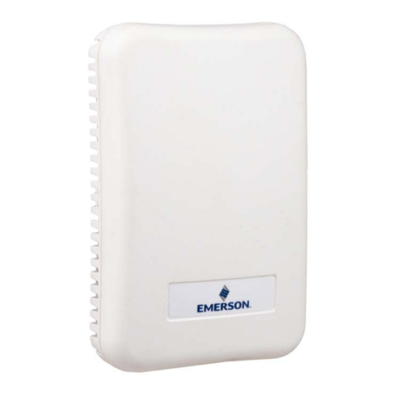
Emerson 203-5752 Руководство по установке - Страница 2
Просмотреть онлайн или скачать pdf Руководство по установке для Аксессуары Emerson 203-5752. Emerson 203-5752 6 страниц. Wall-mounted rh sensor and rh/temperature sensor

Output Scaling
TEMPERATURE OPTION
Sensor Type
OPERATING ENVIRONMENT
Operating Temperature
Operating Humidity
HOUSING
Material
Mounting Holes
AGENCY APPROVAL
Mounting
1. Mount the backplate on the wall in an appropriate location with the "Install This End Up" label positioned in the upper
right corner.
2. Wire the unit as shown (see Wiring section).
3. Attach the front plate.
Wiring
1. Use Belden #8771 shielded three-conductor cable or equivalent.
2. Connect the RED, BLACK, and WHITE wires to the screw terminals the sensor's connector as shown in the image below.
Clip the SHIELD wire.
3. Connect the SHIELD and BLACK wires to the 0V terminal of the input board. Connect the WHITE wire to the SIG terminal
of the input board.
4. Connect the RED wire to the +12V power terminal on the input board.
Document Part # 026-4855 Rev 0
©2022 Emerson Digital Cold Chain, Inc. This document may be photocopied for personal use.
Visit our website at www.climate.emerson.com for the latest technical documentation and updates.
0 to 100% RH
Thermistor, 10k Ohm
0 to 50 °C (32 to 122 °F)
0 to 100% RH non-condensing (Unit will recover from
saturation)
ABS plastic with UL V-0 5VB Flame Class
US and European junction box
*The CE mark indicates RoHS2 compliance. Please refer to the
CE Declaration of Conformity for additional details.
EMC Conformance: Low Voltage Directive 2014/35/EU and EMC
Directive 2014/30/EU.
Page 2 of 6
