HighSecLabs RS40N-4 Руководство по быстрой настройке - Страница 2
Просмотреть онлайн или скачать pdf Руководство по быстрой настройке для Устройство для чтения карт HighSecLabs RS40N-4. HighSecLabs RS40N-4 3 страницы. Secure multi-domain smart card reader

Working with the MDR
One completing the initial MDR configuration steps the MDR
is ready for use allowing simultaneous usage of a single
smartcard with multiple PCs.
Smartcard Removal Behavior
Removing the smartcard from the MDR immediately de-associates
the MDR from all coupled PCs. As a result, smartcard-aware
applications will notice the smartcard absence and respond
accordingly.
For example, a Windows PC that is configured to require
smartcards for user logon may be set to lock the user's desktop
once the smartcard is removed.
Re-associating the MDR after Smartcard
Removal
In order to continue using the smartcard (after it's been removed
from the MDR), the user has to insert the smartcard into the MDR
and complete steps 6-8 in order to re-associated the MDR with all
the corresponding PCs.
MDR Operational Modes
Operational Mode settings determines how Active/Passive PC Modes
are set. For example, when the MDR Operational Mode is set to
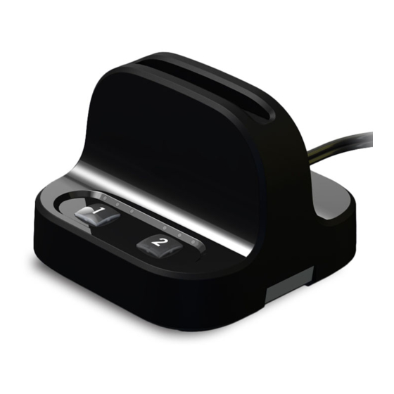
Manual, the user has to manually press the PC Number Button
corresponding to the PC that requires access to the smartcard.
When the MDR Operational Mode is set to dynamic, auto-
association methods are used to determine which PC will be set
as Active.
For example, when the MDR operational mode is set to Activity-
Detection
Auto Association, the MDR will automatically actively
associate itself to the
computer which requires smart card access
based on an activity detection algorithm.
To preset which MDR Operational Mode is in use (Manual / Auto...etc),
there is a hardware dual in-line package (DIP) switch situated in the
underside of the base. See the switch configuration settings in Table
02, column DIP Switch.
Table 02 Operational Modes:
#
Mode
Manually open all
1
channels one by one
7
Single channel active
8
Auto channel
association
Power Requirements:
©2019 All rights reserved. HSL logo and product names are trademarks or service trademarks of HighSecLabs Ltd (HSL).
All other marks are the property of their respective owners. Images for demonstration purposes only. HDC19964 Rev 2.0
Description
The user has to manually activate assosiation with the PCs for the first time, by
pressing channel buttons on the MDR. Once it is connected, it remains active and the
user can keep working with all the PCs.
The User will press the channel button each time for the MDR will associate itself with
the PC. Once the user presses another channel, the previous disconnects.
The User will press channel 1 only once and the MDR will associate itself to all the
connected PCs one by one automatically.
External, wall-mounted power supply 12VDC, 5W maximum
RS20N-4 • RS40N-4 | QUICK CONFIGURATION GUIDE
De-associating the MDR from a Specific PC
Long pressing a PC Number Button is the equivalent of removing
the smartcard only from the PC which corresponds to that button
without affecting other associated PCs. To re-associate that PC
with the MDR, press the PC Number Button to initialize the MDR
(as described in step 7).
The de-association option is useful in any case a user wants to de-
associate the MDR from a specific PC, without interfering with other
PCs which are associated with the MDR.
For example, when a user has to lock PC#1 by removing the
smartcard yet remain logged-on to PC#2, or when a certain PC is
not successfully associated with the MDR and the user wants to
re-associate it.
Reset
Hold one of the connected channel buttons for 7 seconds to reset
the device and its association with the PCs.
DIP Switch Configuration
1. To change the DIP switch settings, hold
the MDR with the underside facing you. In
this position, the DIP switch should be at
the upper right corner.
2. Gently remove the DIP switch cover.
3. The switch includes 8 slides numbered from
1 to 8, ordered from left to right.
4. When pulled down, slide status is OFF. When pulled up, slide status
is ON.
5. To activate an operation mode, pull down its corresponding slide.
6. Multiple slides can be turned OFF (pulled
down) at the same time.
7. Refer to Table 02 to adjust DIP switch settings with your work
scenario.
DIP Switch
1
1 + 7
1 + 8
