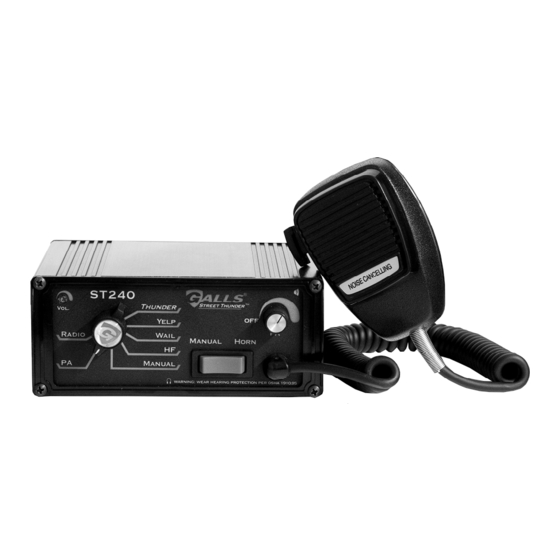
Galls Street Thunder ST240 Руководство по установке и эксплуатации - Страница 5
Просмотреть онлайн или скачать pdf Руководство по установке и эксплуатации для Усилитель Galls Street Thunder ST240. Galls Street Thunder ST240 12 страниц. Siren amplifier

(Electrical Connections CONT'D)
For ease of installation, you can remove
the green connector from the siren while
connecting your wires. Please note that
when referencing terminal numbers using
the wiring diagram on the previous page,
the siren should be held upside down so
the screw heads face UP, as pictured to
the right.
Connections to the terminal block are summarized both in the chart and in the
wiring diagram on the previous page. For more detailed information, review the
section below.
Mandatory Electrical Connections
Ground - Connect terminals 3 & 4 to the negative terminal of the battery.
(You MUST connect both of these terminals!!)
Power - Connect terminals 1 & 2 to a 10-16VDC ignition switched power source
capable of supplying 20A. Be sure to use minimum size #14 AWG wire.
(You MUST connect both of these terminals!!)
Speaker - Connect terminals 5 and 6 to your siren speaker.
(You MUST connect both of these terminals!!)
OPTIONAL ELECTRICAL CONNECTIONS
AUX IN/OUT - These terminals are typically connected to the steering wheel
horn relay. They allow for several functions including siren
operation in HF mode (see page 6), Air Horn activation, or
Manual "step up" function (see page 5).
If you will be using any of these features, cut the wire that
connects the horn relay to the horn. Connect the side from the
relay to terminal 7. Connect the side from the horn to terminal 8.
Review the wiring diagram above and ensure that you have the
AUX Polarity DIP switch set for the correct polarity (see page 4).
(You MUST connect both of these terminals as described
above for proper operation of your vehicle horn!!)
Radio Repeat - If you would like the ability to re-broadcast your two-way radio
over your siren speaker, connect terminals 9 & 10 to the two-way
radio speaker or output connector of the two-way radio.
Backlighting - Connect terminal 11 to the dash lights, ignition switched power,
or other switched 10-16VDC power source. This controls the
backlighting for the face of the siren.
Park/Kill Feature - If you would like the siren to automatically disengage when the
vehicle door is opened or when the vehicle is placed into park,
connect terminal 12 to the dome light, added door switch, or
added park switch. Review the wiring diagram on the previous
page and ensure that you have the PK Polarity DIP switch set for
the correct polarity (see next page).
CPSS-153
(Please note that this is an upside-down view)
-3-
