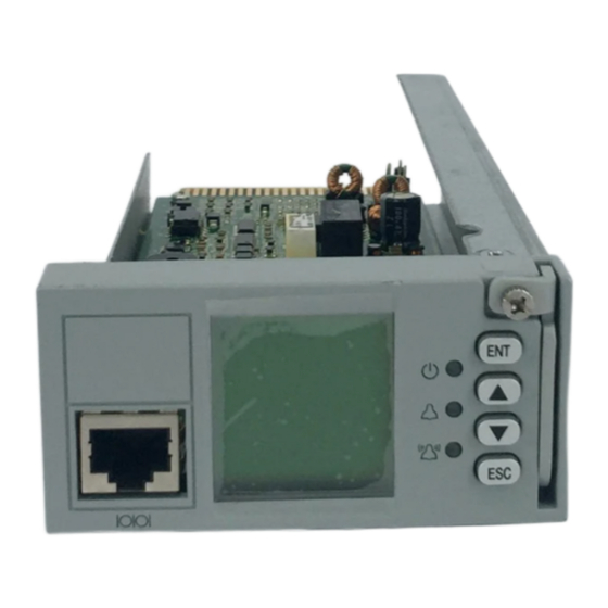
Emerson Network Power M222S Руководство пользователя - Страница 7
Просмотреть онлайн или скачать pdf Руководство пользователя для Контроллер Emerson Network Power M222S. Emerson Network Power M222S 20 страниц.

Weight: <1kg
1.3 Main Functions
1.3.1 Measurement Functions:
Analog value measurement
Item
Battery Current
Bus Voltage
Temperature
Battery String Voltage
Note: The applicable scope of all the measurement resolution is 15 C ~ 30 C
Digital value measurement
Item
Load Fuse
Battery Fuse
DI for Status of bi-stable contactor
DI for Auxiliary Contact of SPD
Extended User DI
Digital output
Item
Extended User DO
Power output
Power Out of External Interface Board
Power Out of Temperature Sensor
LVD drive
The controller has 2 LVD drive outputs that can drive two bi-stable / mono-stable contactors.
1. Bi-stable Contactor: 2A maximum drive current with drive pulse width of 500ms ~ 1s.
2. Mono-stable Contactor: 3A maximum starting current and 1A maximum holding current.
1.3.2 Display And Indicating Functions
The controller has a green LED for indicating operating status, a yellow LED for indicating observation alarm, and a
red LED for indicating major and critical alarms. It also provides a drive output for alarm LED on a system cabinet.
The controller LCD can display the AC parameters, DC parameters, rectifier and battery parameters, operating status,
alarm status, settings, and control parameters.
Table 1-4 Analog value measurement
Quantity
Measurement range
Differential Voltage Signal of Battery Shunt:
1
-100mV ~ 100mV
-48V System: 10Vdc ~ 65Vdc.
1
+24V System: -10Vdc ~ -30Vdc
233uA to 373uA (-40 C ~ 100 C)
2
-48V System: 10Vdc ~ 65Vdc.
4
+24V System: -10Vdc ~ -30Vdc
Table 1-5 Digital value measurement
Quantity
2
Absolute Value: 15V ~ 60V fault, 0 to 1V normal.
4
Absolute Value: < 400mV - 50mV normal, > 400mV + 50mV fault.
1
Absolute Value: 15V ~ 60V open, 0V ~ 1V close.
1
--
4
Expansion board needs to be connected
Table 1-6 Digital output
Quantity
8
Capacity of Contact: 1A / 30Vdc or 125Vac, expansion board is needed
Table 1-7 Power Output
Item
LCU+ Series Controller User Manual
Error is less than ±1% of full measurement
range
± 0.1V, absolute value is 19V to 60V
± 2 C (sensor error is not considered)
± 0.2V, absolute value is 19V to 60V
Parameter
Parameter
Parameter
5VDC, 300mA
10V ~ 12V, 10mA
Chapter 1 Introduction
Resolution
3
