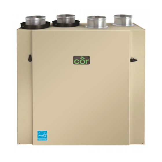
Cor HRVCRSVU1157 Руководство по установке - Страница 5
Просмотреть онлайн или скачать pdf Руководство по установке для Вентилятор Cor HRVCRSVU1157. Cor HRVCRSVU1157 17 страниц. Heat recovery ventilator

Locating the unit
Choose an appropriate location for the unit.
S Within an area of the house where the ambient temperature is
between 50_F (10_C) and 122_F (50_C) (basement, furnace
room, closet, etc.).
S Away from living areas (dining room, living room, bedroom), if
possible.
S So as to provide easy access to the interior of the unit, for
maintenance.
S Close to an exterior wall, so as to limit the length of the insulated
flexible duct to and from the unit.
S Away from hot chimneys and other fire hazards.
S Allow for a power source (standard 3- prong grounding outlet).
S Close to a drain. If no drain is close by, use a pail to collect
run- off.
Hang the unit with the four chains and springs provided. See Fig.
8.
Fig. 8 - Chain spring installation
CAUTION
!
PROPERTY DAMAGE HAZARD
Failure to follow this caution may result in property damage.
Make sure the unit is level.
Planning of the ductwork
S Keep it simple. Plan for a minimum of bends and joints.
S Keep the length of insulated ducts to a minimum.
S Do not ventilate crawl spaces or cold rooms. Do not attempt to
recover the exhaust air from a dryer or a range hood. This would
cause clogging of the filters and recovery module.
DUCT DIAMETER
4 inch (102 mm) round
5 inch (127
) round
mm
6 inch (152 mm) round
S If the house has two floors or more, be sure to plan for at least
one exhaust register on the highest lived- in level.
Calculating duct size
Use Table 2 to ensure that the ducts you intend to install will be
carrying air flows at or under the recommended values. Avoid
installing ducts that will have to carry air flows near the maximum
values and never install a duct if its air flow exceeds the maximum
value.
NOTE: Examples below use imperial units. The same calculation
applies to metric units.
A. Example of calculation:
Problem: The installation requires two exhaust registers (one
for the kitchen, and the other for the bathroom). The registers
are connected to a main duct which will connect to the unit
(high speed performance value of 140 cfm). What size of duct
should be used for the main exhaust duct and for both end
branches leading to the registers? (See Fig. 9.)
Solution: Simplified method. (For a more detailed method of
calculating duct size, refer to the ASHRAE or HRAI HAND-
BOOK.)
Main duct: Table indicates for a 6- in duct: recommended air
flow: 120 cfm, maximum air flow: 180 cfm. The 140 cfm high
speed air flow is close enough to the recommended value (120)
and far away enough from the maximum value (180). There-
fore, a 6- in duct or larger is an appropriate choice for the
main exhaust duct.
End branches: Each end branch will have to transport a 70 cfm
air flow (140 divided by 2). Table 2 indicates for a 5- in
duct: recommended air flow: 75 cfm; maximum air flow: 110
cfm. The high speed air flow of 70 cfm is close enough to the
recommended value (75) and far away enough from the max-
imum value (110). Therefore, a 5- in duct or larger is an ap-
propriate choice for both end branches.
NOTE: A 4- in duct would have been too small because the
maximum acceptable value for a 4- in duct is 60 cfm.
A11197
B. Fig. 10 is an example of a design for a fully ducted system
with a unit having a high speed performance of 140 cfm.
Table 2 – Ductwork Sizing Table
RECOMMENDED AIR FLOW
3
40 CFM (19 L/S or 68 M
/H)
3
75 CFM (35 L/S or 127 M
/H)
3
120 CFM (57 L/S or 204 M
/H)
5
End
branches
5-in ∅,
70 cfm
Main branch
6-in ∅, 140 cfm
Fig. 9 - Main exhaust leading to registers
MAXIMUM AIR FLOW
60 CFM (28 L/S or 102 M
110 CFM (52 L/S or 187 M
180 CFM (85 L/S or 306 M
A11199
3
/H)
3
/H)
3
/H)
