GAMA Electronics RF24V1PR-LS-WPTX Руководство по эксплуатации - Страница 4
Просмотреть онлайн или скачать pdf Руководство по эксплуатации для Приемник GAMA Electronics RF24V1PR-LS-WPTX. GAMA Electronics RF24V1PR-LS-WPTX 6 страниц.
RF24V1PR-LS
Instruction Manual
WWW.GAMAINC.COM
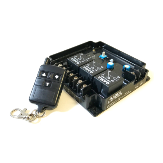
Wiring and Features
Limit Switch Inputs: The receiver has provisions for two normally closed limit switches (not included with the remote control
system). The provision on the receiver terminal block are labeled LIMIT UP and LIMIT DOWN. The receiver must see a +24V
signal on these lines to operate with the remote control or the manual switch in the UP or DOWN direction.
You will need to connect +24VDC to the common terminal on your limit switches and connect the normally closed terminal on
your limit switches to the terminal block positions labeled LIMIT UP and LIMIT DOWN. Wiring your limit switches this way will
provide a continuous +24VDC signal to the receiver when the switch is not activated.
When a limit switch is activated the +24VDC connection to the receiver is opened. If the receiver does not see a +24VDC signal
on the LIMIT UP or LIMIT DOWN terminal the MOTOR OUTPUT will not function when the UP or DOWN operation is activated
on the remote control or the manual switch.
NOTE: IF LIMIT SWITCHES ARE NOT USED FOR ONE OR BOTH DIRECTIONS, YOU MUST SUPPLY A CONSTANT
+24VDC SIGNAL TO THE "LIMIT UP" OR "LIMIT DOWN" POSITION ON THE TERMINAL BLOCK FOR THE MOTOR
OUTPUT TO FUNCTION.
Manual Switch Inputs: The receiver includes inputs for a manual switch to control the polarity reversing output. The manual
control inputs to the receiver are labeled "Down Manual" and "UP Manual". The manual switch inputs are Normally-Open (NO),
and +24 Volts DC is applied to each input to activate the output. A single-pole, double-throw 3-Position momentary-ON, OFF,
momentary-ON switch should be used to control the manual switch inputs. Note: The manual switch inputs when activated will
take priority over the RF transmitter.
Output Current Sensing: The current sensing circuit will monitor the output current and turn off the output and reset the output
for 5-seconds when the output current exceeds the current trip setting of the switch. The output current sensing is adjustable
from 5-Amperes to 35-Amperes. There is a 0.5-second delay in the current sensing to allow for motor inrush.
Page 4 REV A 04/22/20