HIKOKI DV 18V Инструкция по обращению с предметами - Страница 10
Просмотреть онлайн или скачать pdf Инструкция по обращению с предметами для Сверло HIKOKI DV 18V. HIKOKI DV 18V 16 страниц.
However, when drilling 6.5 mm or smaller holes, use a
metalworking drill bit.
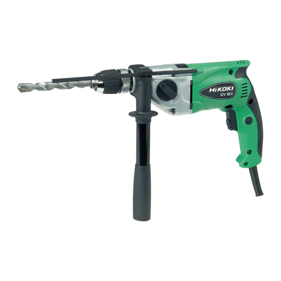
5. Mounting and dismounting of the bit
For keyed chuck (Fig. 1)
(1) Open the chuck jaws, and insert the bit into the chuck.
(2) Place the chuck wrench in each of the three holes in the
chuck, and turn it in the clockwise direction (viewed from
the front side). Tighten securely.
(3) To remove the bit, place the chuck wrench into one of
the holes in the chuck and turn it in the counter-clockwise
direction.
For keyless chuck (Fig. 2)
(1) Mounting the bit
Turn the sleeve counterclockwise and open the chuck.
After inserting the drill bit into the chuck as far it will go,
grip the ring and close the chuck by turning the sleeve
clockwise as viewed from the front.
(2) Dismounting the bit
Grip the ring and open the chuck by turning the sleeve
counterclockwise.
NOTE
When the sleeve does not become loose any further, fi x
the side handle to ring, hold side handle fi rmly, then turn
the sleeve to loosen by hand. (Fig. 3)
6. Check the rotational direction (Fig. 4)
The bit rotates clockwise (viewed from the rear side) by
pushing the R-side of the push button.
The L-side of the push button is pushed to turn the bit
counterclockwise.
(The
and
marks are provided on the body.)
CAUTION:
Always use the impact drill with clockwise rotation, when
using it as an impact drill.
7. Fixing the side handle (Fig. 5)
Attach the side handle to the mounting part.
Rotate the side handle grip in a clockwise direction to
secure it.
Set the side handle to a position that is suited to the
operation and then securely tighten the side handle grip.
To attach a depth gauge on the side handle, insert the
gauge into the U-shaped groove on the side handle,
adjust the position of the depth gauge in accordance with
the desired depth of the hole, and fi rmly tighten the side
handle grip. (Fig. 6)
8. IMPACT to ROTATION changeover (Fig. 7)
Shift the change lever between the right and left positions
to switch easily between IMPACT (rotation and impact)
and ROTATION (rotation only), respectively.
To bore holes in hard materials such as concrete, stone
and tiles, shift the change lever to the right-hand position
(as indicated by the
the combined actions of impact and rotation.
To bore holes in metal, wood and plastic, shift the change
lever to the left-hand position (as indicated by the " "
mark). The drill bit operates by rotational action only, as
in the case of a conventional electric drill.
CAUTION:
○ Do not use the impact drill in the IMPACT function if the
material can be bored by rotation only. Such action will
not only reduce drill effi ciency, but may also damage the
drill tip.
○ Operating the impact drill with the change lever in mid-
position may result in damage. When switching, make
sure that you shift the change lever to the correct position.
9
mark). The drill bit operates by
9. High-speed/Low-speed changeover:
Prior to changing speed, ensure that the switch is in the
OFF position, and the drill has come to a complete stop.
To change speed, rotate the gear shift dial as indicated
by the arrow in Fig. 8. The numeral "1" engraved on the
drill body denotes low speed, the numeral "2" denotes
high speed.
If it is hard to turn the gear shift dial, turn the chuck slightly
in either direction and then turn the gear shift dial again.
HOW TO USE
1. Switch operation
○ When the trigger is depressed, the tool rotates. When the
trigger is released, the tool stops.
○ The rotational speed of the drill can be controlled by
varying the amount that the trigger switch is pulled.
Speed is low when the trigger switch is pulled slightly and
increases as the trigger switch is pulled more.
○ The desired rotation speed can be pre-selected with the
speed control dial.
Turn the speed control dial clockwise for higher speed
and counterclockwise for lower speed. (Fig. 9)
○ Pulling the trigger and pushing the stopper, it keeps
the switched-on condition which is convenient for
continuous running. When switching off , the stopper can
be disconnected by pulling the trigger again.
CAUTION:
If the L-side of push button is pressed for reverse bit
rotation, the stopper cannot be used.
2. Drilling
○ When drilling, start the drill slowly, and gradually
increasing speed as you drill.
○ Always apply pressure in a straight line with the bit. Use
enough pressure to keep drilling, but do not push hard
enough to stall the motor or defl ect the bit.
○ To minimize stalling or breaking through the material,
reduce pressure on drill and ease the bit through the last
part of the hole.
○ If the drill stalls, release the trigger immediately, remove
the bit from the work and start again. Do not click the
trigger on and off in an attempt to start a stalled drill. This
can damage the drill.
○ The larger the drill bit diameter, the larger the reactive
force on your arm.
Be careful not to lose control of the drill because of this
reactive force.
To maintain fi rm control, establish a good foothold, use
side handle, hold the drill tightly with both hands, and
ensure that the drill is vertical to the material being drilled.
MAINTENANCE AND INSPECTION
1. Inspecting the drill bits
Since use of an abraded drill bits will cause motor
malfunctioning and degraded effi ciency, replace the drill
bits with a new one or resharpening without delay when
abrasion is noted.
2. Inspecting the mounting screws
Regularly inspect all mounting screws and ensure that
they are properly tightened. Should any of the screws be
loose, retighten them immediately. Failure to do so could
result in serious hazard.
3. Maintenance of the motor
The motor unit winding is the very "heart" of the power
tool. Exercise due care to ensure the winding does not
become damaged and/or wet with oil or water.